When you press the accelerator and feel your vehicle surge forward, there’s a critical component spinning beneath you that makes it all possible. The drive shaft—a cylindrical metal tube running along your vehicle’s undercarriage—serves as the mechanical link between your engine’s power and your wheels’ motion. For most drivers, this essential component remains invisible and forgotten until something goes wrong. When vibrations shake the floorboard at highway speeds, or a loud clunk echoes during acceleration, the drive shaft is often the culprit.
Understanding how drive shafts work isn’t just technical curiosity—it’s practical knowledge that can save you from dangerous breakdowns and expensive repairs. A failing drive shaft doesn’t just stop your vehicle; in the worst cases, a complete universal joint failure can cause the shaft to drop onto the pavement, dig in, and potentially cause loss of vehicle control at highway speeds. This article explains exactly how drive shafts transmit power, what components make up the system, how to recognize failure symptoms, and when professional service becomes critical for your safety.
Whether you’re an intermediate DIY enthusiast looking to understand your vehicle better, a professional mechanic seeking comprehensive reference material, or a complete beginner trying to make sense of strange noises from underneath, this guide provides the technical depth and practical insights you need. We’ll examine the mechanical principles behind power transmission, explore the precise engineering that allows a spinning metal tube to handle extreme torque while accommodating suspension movement, and identify the warning signs that demand immediate attention.
Understanding your drive shaft system connects directly to other critical drivetrain components. To fully grasp how power flows through your vehicle, you’ll also want to explore how differential systems work and how transfer cases work in four-wheel drive vehicles.
What is a Drive Shaft?
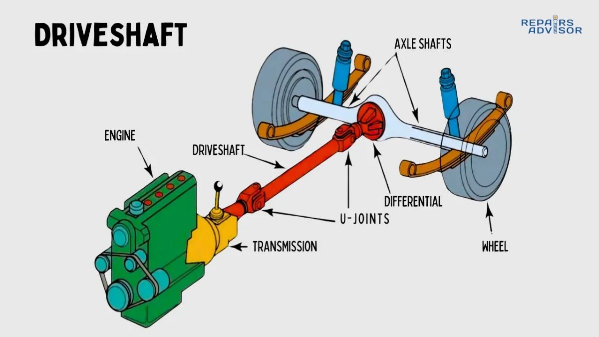
The drive shaft—also called a propeller shaft, prop shaft, or Cardan shaft—is the mechanical component responsible for transmitting rotational power (torque) from your vehicle’s transmission to the differential. This seemingly simple metal tube performs a sophisticated engineering task: it must transfer hundreds of pound-feet of torque while spinning at speeds up to 3,500 RPM, all while accommodating constant changes in length and angle as your suspension moves up and down over bumps and dips in the road.
The drive shaft serves as a mechanical intermediary between drivetrain components that cannot be connected directly due to distance or the need for relative movement between them. In a typical rear-wheel drive vehicle, the transmission sits near the front of the vehicle behind the engine, while the differential sits at the rear axle. The drive shaft bridges this 3-6 foot gap, spinning continuously whenever the vehicle is in gear and moving. The shaft itself is typically constructed from hollow tubular steel or aluminum, with wall thickness ranging from 0.065 to 0.120 inches. This tubular design provides an optimal strength-to-weight ratio—a solid shaft of the same weight would be much weaker, while a thicker-walled tube would add unnecessary weight that reduces efficiency and increases rotational inertia.
Drive Shaft vs. Axle Shaft: Understanding the Difference
Many people confuse drive shafts with axle shafts, but these are distinct components serving different purposes. The drive shaft connects the transmission to the differential—essentially connecting the front and rear sections of the drivetrain. The axle shafts, on the other hand, connect the differential to the individual wheels, transmitting power the final distance to make the wheels turn. All vehicles have axle shafts (either solid axles or independent suspension CV axles), but only rear-wheel drive and four-wheel drive vehicles use traditional drive shafts.
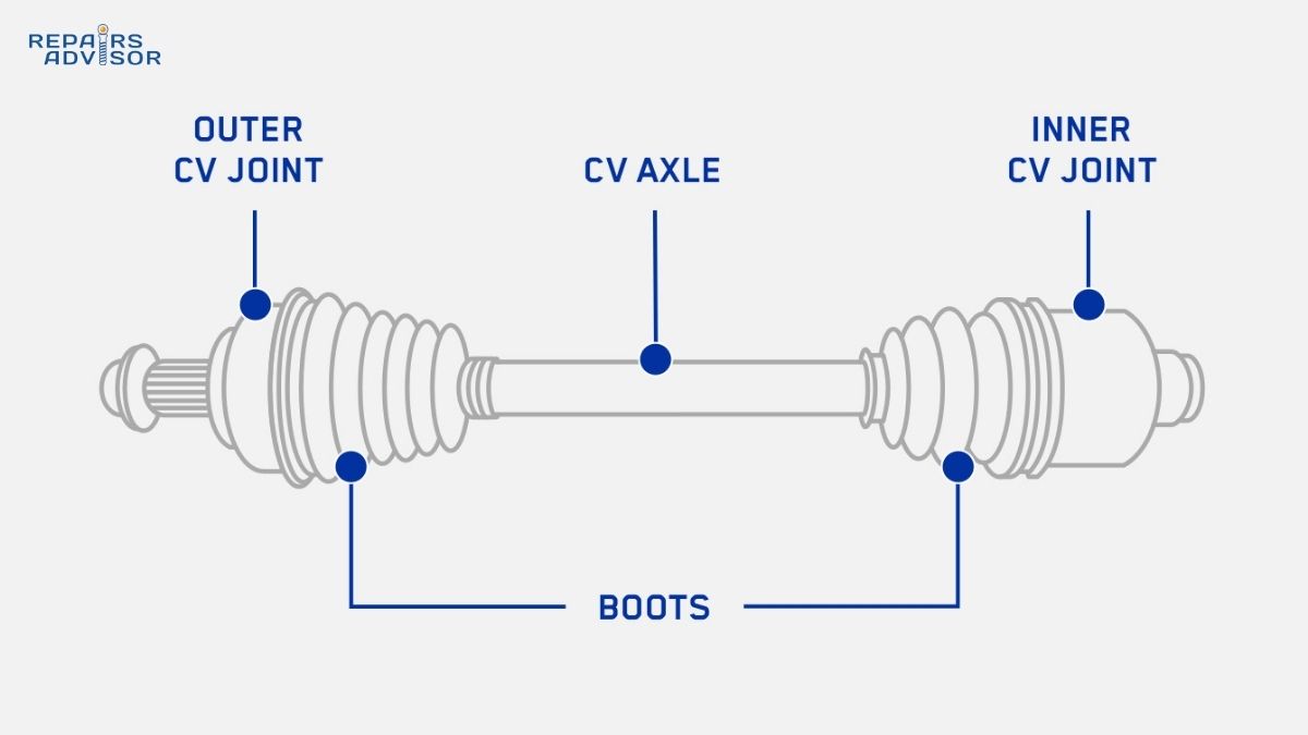
Front-wheel drive vehicles employ a completely different system. Instead of a long drive shaft running to the rear, FWD vehicles use constant velocity (CV) axles that connect the transaxle (combined transmission and differential) directly to the front wheels. These CV axles use a different technology—constant velocity joints—that allows for the extreme angles required by steering and suspension movement at the drive wheels. To understand how these differ from traditional drive shafts, read our detailed guide on how CV joints work.
Vehicle Configuration Differences
Drive shaft configuration varies significantly based on your vehicle’s drivetrain layout:
Rear-Wheel Drive (RWD) vehicles use a single drive shaft running from the transmission output shaft to the rear differential input (pinion). This is the classic configuration found in most trucks, many SUVs, performance cars, and traditional sedans. The shaft typically measures 3-6 feet in length depending on wheelbase, and operates at angles between 3-8 degrees relative to horizontal.
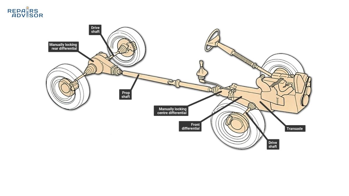
Four-Wheel Drive (4WD) and All-Wheel Drive (AWD) vehicles employ two complete drive shaft assemblies. The rear drive shaft connects the transfer case to the rear differential, similar to a RWD vehicle. The front drive shaft connects the transfer case to the front differential, typically shorter than the rear shaft and operating at steeper angles due to the front axle’s proximity to the transfer case. Understanding how these systems distribute power between axles is crucial—learn more about how AWD systems work.
Front-Wheel Drive (FWD) vehicles don’t use traditional drive shafts at all. The transaxle combines the transmission and front differential into a single housing, with short CV axle shafts connecting directly to the front wheels. This configuration eliminates the need for a long drive shaft running the length of the vehicle.
Professional Insight: When working on 4WD vehicles, always mark the front and rear drive shafts during removal to avoid confusion during reinstallation. The front shaft typically has different length, diameter, and yoke configurations compared to the rear shaft. Installing them in reversed positions can cause severe vibration and potential damage to transfer case or differential seals.
Drive Shaft Components and Their Functions
A drive shaft system consists of multiple precision-engineered components working together to transmit power smoothly and reliably. Understanding each component’s role helps diagnose problems and appreciate the engineering sophistication built into what appears to be a simple metal tube.
The Shaft Tube: Structural Foundation
The main shaft tube forms the structural backbone of the assembly. Most commonly manufactured from seamless DOM (drawn over mandrel) steel tubing, the shaft tube must resist enormous torsional (twisting) forces while remaining light enough to avoid excessive rotational inertia. A typical passenger car drive shaft handles 200-400 lb-ft of torque, while heavy-duty truck shafts may transmit 800-1,200 lb-ft or more.
Material selection significantly impacts performance characteristics. Steel shafts (most common) provide excellent strength and durability at reasonable cost, with typical wall thickness of 0.083 inches for passenger cars and 0.120 inches for trucks. Steel’s higher density means more rotational mass, which slightly reduces acceleration response but provides better vibration damping. Aluminum shafts (performance and luxury vehicles) reduce weight by approximately 50% compared to steel of equivalent strength, improving acceleration and fuel efficiency. However, aluminum requires larger diameter tubes to match steel’s torsional rigidity—a 3.5-inch aluminum shaft might replace a 3-inch steel shaft. Carbon fiber composite shafts (high-performance and exotic vehicles) offer the ultimate strength-to-weight ratio, capable of handling extreme torque with minimal mass, but at significantly higher cost.
The shaft tube must be manufactured to extremely tight tolerances. Total indicated runout (TIR) typically must be held to 0.010 inches or less—any deviation causes vibration at operating speeds. The shaft undergoes high-speed dynamic balancing during manufacturing, with small weights welded or clipped to specific locations to eliminate vibration. These balancing weights are critical: removing even one weight will cause severe vibration. If you need to mark a drive shaft for reinstallation, never use welding, grinding, or methods that add or remove material—use paint markers only.
Universal Joints: Accommodating Angular Movement
Universal joints (U-joints) rank among the most critical components in the drive shaft assembly. These cross-shaped devices allow the drive shaft to transmit power through angles that constantly change as the suspension moves. A typical U-joint consists of a cross-shaped center piece with four bearing caps, each containing needle bearings that allow the cross to rotate smoothly within the yoke. The design dates back to the 16th century Cardan joint, though modern automotive applications use precision needle bearings and high-strength alloy steel construction.
U-joints must accommodate operating angles typically ranging from 3-15 degrees, though angles beyond 8 degrees generally require double-cardan constant velocity joints for smooth operation. The engineering challenge lies in the fact that U-joints operating at angles create small speed variations—the output shaft speeds up and slows down slightly twice per revolution relative to the input shaft. This inherent characteristic of single U-joints requires careful attention to drive shaft phasing: the yokes at each end of the shaft must be installed in precise alignment (in phase) so that the speed variations from the front U-joint are canceled by the rear U-joint.
Most U-joints fall into two categories: greaseable U-joints include zerk fittings that allow periodic lubrication with grease gun, typically requiring service every 50,000-75,000 miles. Sealed-for-life U-joints contain permanent lubrication and cannot be serviced—when they wear out, replacement is the only option. Professional mechanics often prefer greaseable U-joints for their longer service life potential, though sealed joints reduce maintenance requirements for average vehicle owners.
U-joint failure typically announces itself through clicking, clunking, or squeaking sounds, especially during initial acceleration or when changing between forward and reverse. A simple inspection can detect wear: with the vehicle safely supported on jack stands, grasp the drive shaft near each U-joint and try to move it up-down and side-to-side. Any perceptible play indicates worn bearings requiring immediate replacement. Understanding bearing systems throughout your vehicle helps diagnose related issues—explore how wheel bearings work to see similar principles in action.
Slip Yoke: Accommodating Length Changes
While U-joints handle angular changes, the slip yoke addresses length changes. As your suspension compresses over bumps or extends into dips, the distance between the transmission and differential constantly changes—sometimes by 2-3 inches over the full suspension travel. The slip yoke prevents this length change from binding the drivetrain or pulling components apart.
The slip yoke design features an internally splined tube that slides over the externally splined transmission output shaft. As the drive shaft needs to lengthen or shorten, the yoke slides in or out smoothly along these splines. A dust boot or seal at the transmission prevents contamination from entering the sliding interface, though many vehicles lack this protection, leading to accelerated wear in dusty or salty environments.
Proper lubrication is absolutely critical for slip yoke longevity. The splined interface requires grease to prevent binding, wear, and corrosion. Many modern vehicles use sealed slip yokes with permanent lubrication, but older designs may require periodic greasing through a zerk fitting. Lack of lubrication creates a distinctive clunking sound during initial acceleration as the yoke binds momentarily before breaking free. This “transmission clunk” is often misdiagnosed as a transmission problem when it’s actually a dry slip yoke—a quick shot of grease often eliminates the noise immediately.
Some newer vehicles use a slip-in-tube design rather than a slip yoke on the transmission. This design places the length compensation mechanism at the center bearing location or integrates it into the shaft itself. This configuration allows the use of a fixed flange connection at the transmission, simplifying sealing and reducing the chance of fluid leakage.
Center Support Bearing: Supporting Long Shafts
Vehicles with long wheelbases—full-size trucks, extended cab pickups, large SUVs—cannot use a single-piece drive shaft due to critical speed limitations. When a hollow tube spins at high RPM, it can reach a natural resonant frequency where it begins to whip or deflect excessively, leading to catastrophic failure. The critical speed of a shaft is determined by its length, diameter, wall thickness, and material properties. For steel tubing commonly used in automotive applications, practical length limits are approximately 60-72 inches before critical speed issues become problematic at highway speeds.
The solution is a two-piece drive shaft assembly with a center support bearing mounted to the vehicle’s frame or underbody at the midpoint. This bearing consists of a precision ball bearing mounted in a rubber isolator, which is then bolted to a frame crossmember. The bearing supports the middle of the drive shaft assembly, effectively creating two shorter shafts from a single long one, with each section operating well below its critical speed.
The rubber isolator serves two purposes: it holds the bearing while allowing slight movement to accommodate drivetrain flex, and it dampens vibration transmission to the vehicle structure. Over time—typically 75,000-120,000 miles—this rubber deteriorates from heat, oil contamination, and age. As the rubber deteriorates, the bearing loses its precise alignment, causing vibration that increases with vehicle speed. A worn center bearing typically creates an intense vibration at highway speeds (50-75 mph) that feels like it’s coming from directly beneath the vehicle’s center. Unlike wheel balance issues that tend to affect steering wheel vibration, center bearing vibration is typically felt more strongly through the seat and floor.
Replacement requires careful attention to shaft phasing and alignment. The two shaft sections must be installed so their yokes are in phase with each other, ensuring smooth power transfer. Professional shops use angle finders and dial indicators to verify proper installation—incorrect phasing causes vibration even with new components.
Yokes and Flanges: Connecting to Drivetrain
The various yokes and flanges connect the drive shaft to the transmission, transfer case, and differential. Each type serves a specific purpose and must be correctly identified during service:
End yokes slip over the transmission or transfer case output shaft and are typically held in place with a large nut or retained by a snap ring. These yokes contain the slip splines that allow length compensation.
Flange yokes bolt directly to a companion flange on the differential’s pinion shaft using four bolts. The bolts typically torque to 50-80 lb-ft depending on vehicle size and must be torqued evenly in a criss-cross pattern to ensure proper alignment and prevent distortion.
Tube yokes (also called weld yokes) are permanently welded to the ends of the shaft tube and hold the U-joints. These yokes must be precisely aligned during manufacturing—even slight misalignment creates vibration.
When replacing a drive shaft or servicing U-joints, always mark the orientation of yokes before disassembly. The assembly is balanced as a unit, and reinstalling components in different orientations destroys the balance, causing severe vibration.
Balancing Weights: Vibration Elimination
Every drive shaft undergoes dynamic balancing during manufacturing. The shaft assembly is spun at high speed (typically 3,000-5,000 RPM) on a computerized balancing machine that measures vibration and calculates the exact weight and placement needed to eliminate it. Small metal weights are then welded or clipped to specific locations on the shaft tube.
These balancing weights are absolutely critical to smooth operation. Never remove or relocate balancing weights—doing so will cause severe vibration. If you notice a weight has fallen off, the shaft must be professionally re-balanced. Similarly, never weld, grind, or drill on a drive shaft, as adding or removing even small amounts of material destroys the balance. If you need to mark a shaft for orientation during service, use paint markers only.
Beginner-Friendly Explanation: Think of a drive shaft like a bicycle chain connecting your pedals to the back wheel—but instead of a flexible chain, it’s a rigid metal tube spinning at very high speed. The U-joints work like your wrist, allowing you to change the angle between your forearm and hand while still being able to grip and turn something. The slip yoke is like a telescope that can extend or shorten, keeping the connection between two points even as the distance changes. All these parts work together so smoothly that you never think about them—until something wears out and starts making noise.
How Drive Shafts Work: Step-by-Step Operation
Understanding the drive shaft’s operation requires following the power flow from the engine through to the wheels, examining how each component contributes to smooth, efficient power transmission.
Step 1: Power Reception from Transmission
The journey begins at the transmission or transfer case output shaft. The engine generates rotational power (torque) which flows through the transmission. In rear-wheel drive vehicles, the transmission sits near the front of the vehicle—behind the engine—while the differential resides at the rear axle. The transmission’s job is to multiply torque at lower speeds and adjust gear ratios for different driving conditions, but ultimately all this power must be transmitted to the rear wheels.
The transmission output shaft typically rotates at speeds between 1,000 and 3,500 RPM depending on the selected gear and vehicle speed. In first gear at low speed, the output shaft might spin at 1,200 RPM while transmitting 400 lb-ft of torque. In overdrive at highway speed, the shaft might spin at 2,800 RPM while transmitting only 150 lb-ft of torque—less torque is needed to maintain speed than to accelerate. The drive shaft must handle this wide range of operating conditions smoothly and reliably.
The connection between transmission and drive shaft varies by design. Vehicles with slip yokes have the splined yoke sliding onto the transmission output shaft splines, retained by a snap ring or lock nut. Vehicles with flange connections bolt the drive shaft directly to a transmission output flange. Understanding how the transmission itself operates provides valuable context—read our comprehensive guide on how automatic transmissions work or how manual transmissions work depending on your vehicle type.
Step 2: Torque Transfer Through the Shaft
Once the shaft begins rotating, it must transmit the twisting force (torsional load) from the input end to the output end. This appears simple—it’s just a spinning tube—but the engineering involved is sophisticated. The shaft experiences enormous torsional stress: a 3-inch diameter steel shaft transmitting 300 lb-ft of torque experiences shear stress approaching 15,000 PSI in the material.
The hollow tubular design provides the optimal solution to handle these forces while minimizing weight. A hollow tube is much more efficient at resisting torsion than a solid rod of the same weight—the material at the outer diameter does most of the work resisting torsional deflection, while material near the center contributes little. This is why drive shafts use hollow tubes rather than solid rods.
The shaft must remain perfectly straight and balanced during operation. Any bend, even a few thousandths of an inch, creates vibration as the bent section whips around during rotation. This whipping effect amplifies at higher speeds, potentially reaching critical speed—a resonant frequency where the shaft deflects excessively and can fail catastrophically. This is why shaft length is limited and why longer wheelbases require two-piece shafts with center bearings.
Material selection directly impacts performance. Steel shafts provide excellent torsional rigidity and durability but add rotational mass that slightly reduces acceleration response. Aluminum shafts reduce weight by half but require larger diameters to match steel’s rigidity. Carbon fiber provides exceptional strength-to-weight ratios but costs significantly more—typically found only in high-performance or exotic vehicles where the cost is justified by performance gains.
Step 3: Accommodating Angles Through U-Joints
As the vehicle travels down the road, the suspension constantly moves up and down, causing the angle between the transmission output and the drive shaft to change continuously. The front U-joint accommodates these angular changes while maintaining power transfer. When the suspension compresses, the angle increases; when it extends, the angle decreases. The U-joint must handle these variations smoothly without binding or causing vibration.
The engineering challenge with U-joints is that they create small speed variations when operating at angles. If the input shaft rotates at constant 2,000 RPM through a U-joint at a 5-degree angle, the output shaft speeds up and slows down twice per revolution, varying between approximately 1,995 and 2,005 RPM. This variation is imperceptible at small angles but becomes more pronounced as angles increase.
This is where proper phasing becomes critical. The drive shaft has U-joints at both ends—one at the transmission and one at the differential. If both yokes are installed in phase (aligned with each other), the speed variation created by the front U-joint is exactly canceled by the rear U-joint operating at a similar angle. The result is smooth, constant-velocity power transmission even though neither individual U-joint provides constant velocity.
The mathematics behind this cancellation requires that both U-joints operate at approximately equal angles. If the front U-joint operates at 5 degrees and the rear at 8 degrees, perfect cancellation doesn’t occur and some residual vibration results. Professional drive shaft installations require measuring operating angles with precision protractors and adjusting suspension mounting points if necessary to achieve optimal angles. Target angles are typically 3-5 degrees at both ends, with the angles within 1 degree of each other.
Professional Technical Note: To calculate acceptable operating angles, use the formula: Maximum angle (degrees) = 18,000 / RPM. For a shaft operating at 3,000 RPM, maximum continuous angle is approximately 6 degrees. Angles beyond this cause accelerated U-joint wear and heat generation. Always verify angles after suspension modifications—lift kits commonly create excessive angles that destroy U-joints prematurely.
Step 4: Length Compensation Through the Slip Yoke
Simultaneously with angular changes, the suspension movement also changes the distance between the transmission and differential. When the suspension compresses over a bump, this distance decreases; when it extends into a dip, the distance increases. These length changes can amount to 2-3 inches over full suspension travel. Without some mechanism to accommodate this, the drivetrain would bind or pull apart.
The slip yoke solves this problem elegantly. As the shaft needs to lengthen, the slip yoke slides out of the transmission output shaft along the splines. As it needs to shorten, it slides back in. This sliding action occurs continuously and automatically as you drive, requiring no driver input or electronic control—it’s purely mechanical, driven by the geometric changes in the drivetrain.
Proper lubrication of the slip yoke splines is absolutely essential for smooth operation. Without adequate lubrication, the yoke can bind momentarily before breaking free, creating a characteristic clunking sound during initial acceleration. This sound is often misdiagnosed as a transmission problem, but it’s typically just a dry slip yoke that needs lubrication. A single shot of grease into the spline area (if a grease fitting is provided) often eliminates the noise immediately.
The slip yoke typically has a dust boot or seal that prevents dirt and moisture from entering the spline area. This boot deteriorates over time from heat and age. When it fails, contaminants enter the splines, accelerating wear and potentially causing binding. Regular inspection of this boot during routine maintenance can prevent problems—replacing a torn boot costs far less than replacing a worn transmission output shaft.
Some vehicles use alternative designs for length compensation. Two-piece shafts may incorporate a slip joint at the center bearing location rather than at the transmission. This allows a solid flange connection at both the transmission and differential, eliminating the potential for slip yoke problems but adding complexity at the center bearing.
Step 5: Power Delivery to the Differential
At the rear of the drive shaft, power transfers through the final U-joint to the differential’s pinion yoke. The drive shaft typically bolts to the differential’s companion flange using four grade-8 bolts torqued to specification—typically 50-80 lb-ft depending on vehicle size. These bolts must be torqued properly and checked for proper thread engagement. Using the wrong bolt length can cause the bolt to bottom out before fully clamping the joint, leading to looseness and vibration.
The differential’s pinion gear receives the rotating power from the drive shaft and transfers it to the ring gear, which drives the axle shafts that turn the wheels. The gear ratio in the differential (commonly 3.73:1, 4.10:1, etc.) means the pinion gear rotates 3.73 or 4.10 times for every one rotation of the wheels. This gearing provides the final torque multiplication and speed reduction in the drivetrain.
Understanding how the differential distributes power between the wheels completes the picture of how your vehicle’s drivetrain operates. For comprehensive information on differential operation, read our detailed guides on how differential systems work and how limited slip differentials work.
Real-World Operating Conditions
Drive shafts operate under demanding conditions. They must function reliably across temperature ranges from -40°F in winter conditions to 250°F from transmission and differential heat in demanding driving. They spin at speeds up to 3,500-4,000 RPM, limited by critical speed considerations. They handle torque ranging from 100 lb-ft in small economy cars during steady cruising to over 1,000 lb-ft in heavy-duty trucks during maximum towing.
With proper maintenance, drive shafts typically last 120,000-200,000 miles before requiring component replacement. The weakest links are usually the U-joints, which wear from constant articulation under load. The center bearing (on two-piece shafts) typically requires replacement between 75,000-150,000 miles as the rubber isolator deteriorates. The shaft tube itself rarely fails unless damaged by impact or severe corrosion—it’s the moving parts that wear out.
Understanding these operating parameters helps you appreciate why proper maintenance is critical. The forces involved are enormous, the speeds are high, and the operating environment is harsh. Regular inspection and timely replacement of worn components prevents catastrophic failures that can leave you stranded or, in worst-case scenarios, cause loss of vehicle control.
Common Drive Shaft Problems and Symptoms
Drive shaft problems typically announce themselves through vibration, noise, or handling changes. Learning to recognize these symptoms helps you address issues before minor problems become major failures. Most drive shaft failures are progressive—they give warning signs long before complete failure occurs. Paying attention to these warnings and taking prompt action keeps you safe and minimizes repair costs.
Intense Vibration: The Most Common Symptom
Vibration represents the most frequent symptom of drive shaft problems. Unlike tire balance issues or engine vibrations that might be felt through the steering wheel, drive shaft vibration typically transmits through the floor, seat, and lower body of the vehicle. The vibration is proportional to drive shaft speed—it increases as vehicle speed increases and decreases when you slow down.
Worn U-joints cause the most common vibration problems. As the needle bearings in U-joints wear, they develop play that allows the shaft to whip slightly during rotation. This whipping creates an out-of-balance condition that intensifies with speed. The vibration typically becomes most noticeable between 50-70 mph, right in the typical highway cruising range. The characteristic of worn U-joint vibration is that it’s speed-sensitive but not load-sensitive—the vibration intensity depends more on how fast you’re going than how hard you’re accelerating.
Worn center bearings (on two-piece shafts) create similar symptoms but with a different character. Center bearing vibration often feels more severe and may be accompanied by a growling or rumbling sound. The vibration typically worsens with speed but may temporarily decrease at certain specific speeds where resonance conditions change. As center bearing rubber isolators deteriorate, they allow the bearing to shift position slightly, causing misalignment between the front and rear shaft sections.
Out-of-balance conditions from damaged or missing balancing weights create vibration that may feel smoother than U-joint vibration but is persistent across a wide speed range. If someone has removed a balancing weight—perhaps knocked off by road debris—or if the shaft has been damaged, rebalancing is required. Unlike U-joint vibration that develops gradually as wear increases, balance-related vibration often appears suddenly after an impact or after service work if the shaft was reinstalled in a different orientation.
Incorrect operating angles after suspension modifications create vibration that may be worse during acceleration or deceleration. Lift kits commonly create excessive drive shaft angles that cause vibration and accelerated U-joint wear. This type of vibration often improves if you put the transmission in neutral while coasting—disconnecting the engine’s torque pulses reduces the vibration.
One diagnostic trick: if vibration is present during acceleration but decreases significantly when you lift off the throttle or put the transmission in neutral while coasting, the problem is likely drive shaft-related rather than tire balance or wheel bearing issues. Tire and bearing problems persist regardless of power application, while drive shaft problems often change with load conditions.
For comparative diagnosis, understanding how suspension components can create similar vibrations helps isolate drive shaft problems from other issues. Review our guide on how to tell if your front shock absorber is failing to understand how suspension issues might present with similar symptoms.
Clunking and Knocking Noises
Clunking sounds from underneath the vehicle rank as the second most common drive shaft symptom. These sounds result from excessive play in worn components, allowing parts to move enough that they impact each other when load direction changes.
Worn U-joints with excessive play create a distinctive clunk when you initially accelerate from a stop or when shifting between drive and reverse. As torque loads the drivetrain in one direction, the play in the U-joint allows components to shift slightly before solidly engaging. When torque reverses direction, the components must travel through this free play again, creating the clunking sound. The clunk is most noticeable during the first moment of acceleration because that’s when torque loading changes most dramatically. Once you’re accelerating steadily, the clunk disappears because torque direction remains constant.
The severity of U-joint clunking indicates wear progression. A faint single clunk during initial acceleration suggests early wear—the U-joint might have another 10,000-20,000 miles of life remaining. A loud, multiple clunking sound—”clunk-clunk-clunk”—indicates severe wear and imminent failure. At this stage, the U-joint could fail completely at any time, potentially dropping the drive shaft onto the pavement.
Worn slip yoke splines create a similar clunking sound but with different timing. Slip yoke clunk typically occurs during the initial inch of movement when starting from a stop—the loose splines allow the shaft to rotate slightly before engaging solidly. Some slip yoke clunking is normal in older vehicles, but loud or worsening clunks indicate significant wear. The solution is often simple: if a grease fitting is present, injecting grease into the slip yoke often reduces or eliminates the clunk by taking up some of the clearance between the splines.
Loose differential or transmission mounting can create sounds similar to drive shaft problems. The differential housing is typically bolted to the axle housing through rubber bushings. If these bushings deteriorate or if mounting bolts loosen, the entire differential can shift slightly under torque loading, creating clunks. Similarly, worn transmission mounts allow the transmission to shift, affecting drive shaft alignment and potentially causing noise.
Distinguishing between these various sources requires careful diagnosis. The timing of the clunk (when it occurs during the power application cycle) and whether it’s a single event or multiple repeated clunks helps identify the source. Professional mechanics often use a helper to operate the vehicle while they observe underneath to pinpoint exactly where the noise originates.
Safety Critical: Any loud clunking from the drivetrain requires immediate professional inspection. Worn U-joints can fail completely without warning, dropping the drive shaft onto the road. At highway speeds, this creates an extremely dangerous situation where the shaft can dig into the pavement and potentially cause loss of vehicle control.
Squeaking Sounds at Low Speed
A squeaking sound from underneath the vehicle during acceleration or deceleration, most noticeable at speeds between 15-35 mph, typically indicates a U-joint that needs lubrication or is beginning to fail. The squeak occurs when the U-joint operates without adequate lubrication—metal bearing surfaces rub against each other, creating the characteristic high-pitched sound.
If your vehicle has greaseable U-joints with zerk fittings, this squeak often disappears immediately after proper greasing. Use a grease gun to inject high-quality moly-based grease until you see fresh grease purge from all four bearing seals—this ensures old contaminated grease is completely flushed out. However, if squeaking persists after thorough greasing, the U-joint bearings are likely worn beyond service life and require replacement. No amount of additional grease will restore worn bearings.
Sealed-for-life U-joints don’t have grease fittings—when they squeak, replacement is the only option. The sealed design prevents relubrication, so once the internal grease deteriorates or contamination enters, the U-joint will continue to deteriorate until it fails.
Some technicians recommend greasing U-joints every oil change as preventive maintenance on vehicles with greaseable joints. This frequent greasing prevents bearing wear and dramatically extends U-joint life. However, excessive greasing can cause grease to leak past the seals and contaminate brake components, so use the minimum amount needed to see fresh grease purge at the seals.
Difficulty Turning or Handling Problems
When a drive shaft problem affects your vehicle’s handling or steering response, the situation has become serious. A severely worn or seized U-joint can bind, preventing the differential from performing its essential function of allowing the inside and outside wheels to rotate at different speeds during turns. This manifests as resistance during steering, unusual tire scrubbing sounds, or a feeling that the vehicle wants to go straight even when you turn the wheel.
In extreme cases, a completely seized U-joint prevents any relative motion between the shaft and the yoke, essentially creating a solid connection that cannot articulate. When this occurs, every suspension movement tries to bend or break the shaft, and every turn of the steering wheel creates binding forces throughout the drivetrain. The vehicle becomes dangerous to drive and may not be controllable in emergency maneuvers.
If you experience any change in steering feel, handling response, or hear unusual sounds during turns that seem to come from underneath the vehicle, stop driving immediately and have the vehicle towed for professional inspection. Attempting to drive with a severely worn or seized U-joint risks complete failure and potential loss of vehicle control. The repair cost is far less than the potential consequences of a crash caused by drive shaft failure.
Shuddering During Acceleration
A shuddering or juddering sensation during acceleration, particularly when accelerating from low speeds up to about 40 mph, often indicates problems with the center bearing on two-piece drive shafts or worn U-joints beginning to bind. Unlike smooth vibration that feels like a continuous buzz, shuddering feels like a series of rapid kicks or jerks transmitted through the vehicle body.
Worn center bearing rubber isolators allow the bearing to shift position slightly, causing misalignment between the front and rear shaft sections. This misalignment creates binding and releasing as the shaft rotates, producing the shudder. The problem typically worsens under load—hard acceleration increases the shudder, while coasting may reduce it.
Incorrect drive shaft phasing creates shudder even with new components. If a shaft is reinstalled with the yokes out of phase, or if a two-piece shaft is assembled incorrectly, the speed variations from the U-joints don’t cancel properly, creating the shuddering sensation. Professional shops use precise marking and measurement techniques during assembly to prevent phasing problems.
Shuddering can also result from other drivetrain problems not related to the drive shaft. Worn transmission mounts, failing torque converters (automatic transmissions), or clutch problems (manual transmissions) can create similar sensations. Proper diagnosis requires systematic inspection and often a test drive by an experienced technician who can distinguish between these various possibilities. To understand related transmission issues, see our comprehensive guide on how torque converters work.
Visual Damage and Wear Indicators
Regular visual inspection can identify drive shaft problems before they cause symptoms or failures. If you’re comfortable working under your vehicle, periodic inspection takes only a few minutes and can prevent serious problems:
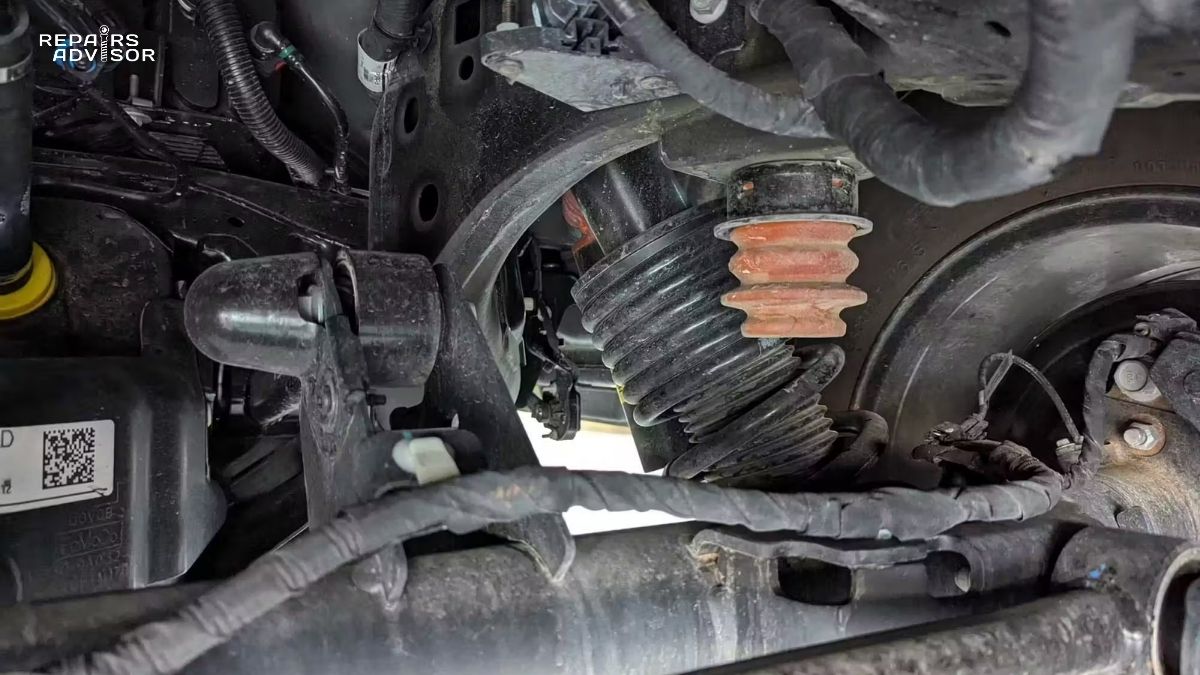
Torn or damaged boots and seals: CV joint and U-joint boots protect critical components from contamination. A torn boot allows grease to escape and dirt/moisture to enter, rapidly accelerating wear. Check boots for cracks, tears, or grease leakage. Any boot damage requires immediate replacement—the cost of a new boot is far less than the cost of replacing the joint it protects.
Rust or corrosion on the shaft tube: Surface rust on the shaft tube is cosmetic, but deep corrosion that pits the surface or causes wall thinning is serious. Corrosion typically attacks the shaft in areas where road salt and moisture accumulate. Check particularly around welds and at the ends of the shaft where moisture tends to collect. Severe corrosion weakens the shaft and can lead to catastrophic failure at highway speeds.
Bent or dented shaft: Any visible bend in the shaft or significant dent requires shaft replacement. Even small bends create imbalance and vibration. Dents weaken the shaft structure and can propagate into cracks under repeated stress cycles. Never attempt to straighten a drive shaft yourself—specialized equipment is required to restore proper straightness and balance.
Missing or loose balancing weights: Look for signs that balancing weights have fallen off—you might see remaining weld spots where weights were attached, or you might find a weight hanging by a single weld. Any missing weight requires professional rebalancing before continued operation.
Grease leakage or dry joints: Grease escaping from U-joint seals appears as dark grease spatter on the shaft tube and surrounding components. While slight grease seepage at seals is normal after greasing, heavy leakage indicates seal failure. Conversely, completely dry-looking U-joints on older vehicles suggest lack of maintenance and potential internal wear.
Cracks near weld points: Inspect where yokes are welded to the shaft tube. Cracks typically start at welds due to stress concentration. Any crack, no matter how small, requires immediate shaft replacement—cracks propagate rapidly under the alternating stress of rotation and can cause sudden catastrophic failure.
For beginners working under vehicles for the first time: always use proper jack stands rated for your vehicle’s weight, never rely solely on a hydraulic jack. Place jack stands on solid frame or axle mounting points, use wheel chocks on the wheels remaining on the ground, and work on level, solid ground. Wear safety glasses to protect from rust, dirt, and debris that can fall into your eyes when looking up from underneath.
Drive Shaft Maintenance and Inspection
Proactive maintenance dramatically extends drive shaft life and prevents unexpected failures. While drive shafts are relatively durable, they operate in a harsh environment and certain components require periodic service.
Recommended Maintenance Schedule
Every 30,000 miles or annually: Perform visual inspection for damage, leaking grease, worn boots, rust, and physical damage. Check for play in U-joints by attempting to move the shaft perpendicular to its axis—any perceptible movement indicates wear requiring attention. This inspection takes only 10-15 minutes but can identify problems before they cause symptoms.
Every 50,000-75,000 miles: Lubricate greaseable U-joints thoroughly. Use a grease gun with high-quality moly-based CV joint grease (not general-purpose grease—CV joint grease contains additives specifically formulated for the extreme pressures in U-joints). Inject grease until fresh grease purges from all four bearing seals, ensuring old contaminated grease is completely displaced. This preventive lubrication can double or triple U-joint life.
After suspension modifications: Any suspension lift kit, leveling kit, or component replacement that changes ride height requires drive shaft angle verification. Measure operating angles at both ends of the shaft using a precision angle finder or smartphone app designed for this purpose. Angles should be 3-5 degrees at each end and within 1 degree of each other. Excessive angles cause rapid U-joint wear and vibration—CV-style constant velocity joints or slip yoke eliminator kits may be required for severe lift applications.
Following impact damage: If you strike road debris, a curb, or encounter any significant impact to the undercarriage, inspect the drive shaft even if no symptoms are apparent. Impacts can bend the shaft or knock off balancing weights, causing problems that may not appear immediately but will worsen over time.
DIY U-Joint Inspection Procedure
Checking U-joint condition requires safely accessing the underside of your vehicle. This is an intermediate-level DIY task that requires proper safety equipment:
- Safety first: Park on level ground, set parking brake, place wheel chocks behind wheels that will remain on ground, and properly position jack stands rated for your vehicle’s weight under frame or axle mounting points. Never work under a vehicle supported only by a hydraulic jack.
- Access the drive shaft: Crawl under the vehicle with a flashlight. The drive shaft is the cylindrical tube running from the transmission toward the rear differential.
- Check for play: Wearing work gloves, firmly grasp the drive shaft near each U-joint. Try to move it up and down perpendicular to the shaft axis, then side to side. There should be no perceptible movement—any play you can feel indicates worn bearings.
- Listen and feel: While moving the shaft, listen for clicking sounds and feel for clunking—these indicate significant wear. Rotate the shaft by hand (transmission in neutral) and feel for rough spots or binding.
- Visual inspection: Look for rust-colored staining around U-joint caps (indicates water contamination), grease leakage (seal failure), or loose bearing caps. Examine the U-joint cross for any visible wear grooves in the bearing surface.
Normal condition: No perceptible play, smooth rotation, no noise when moved. Marginal condition: Very slight play barely detectable, slight clicking if you move the shaft forcefully. Monitor closely and budget for replacement soon. Failed condition: Obvious play, loud clicking or clunking, visible damage. Replace immediately—do not continue driving.
Understanding lubrication principles throughout your vehicle helps maintain all systems properly. For broader context on lubrication systems, read our guide on how oil filters work.
Proper Lubrication Techniques
For vehicles with greaseable U-joints (identifiable by zerk grease fittings on the U-joint caps), proper lubrication is critical for long life:
Use the correct grease: High-quality moly-based grease specifically formulated for CV joints and U-joints. Do not use general-purpose chassis grease—it lacks the extreme pressure additives needed for the high loads in U-joints. Popular brands include Lucas Red ‘N’ Tacky, Valvoline Moly-Fortified, or OEM-specified greases.
Inject until purge: Attach a grease gun to the zerk fitting and pump until you see fresh, clean grease purge from all four bearing seals around the U-joint cap. This typically requires 3-5 pumps of a standard grease gun. Seeing grease purge at all four seals ensures the old grease is completely flushed out and new grease reaches all bearing surfaces.
Don’t over-grease: Once fresh grease appears at all seals, stop pumping. Excessive grease can damage seals or cause grease to escape and contaminate brake components or exhaust systems. It’s better to grease more frequently with moderate amounts than to force excessive grease in a single session.
Timing matters: Grease U-joints when they’re warm if possible—drive the vehicle for 10-15 minutes before greasing. Warm grease flows more easily and distributes better throughout the bearing. However, be careful not to touch hot exhaust components when working underneath a warm vehicle.
Sealed U-joints: If your vehicle has sealed-for-life U-joints (no grease fittings), no lubrication is possible or needed. These joints contain permanent lubrication sealed during manufacturing. When they wear out, replacement is the only option—they cannot be serviced.
Component Replacement Guidelines
U-joints should be replaced at the first sign of play, noise, or binding. Service life varies widely: well-maintained greaseable U-joints might last 150,000+ miles, while neglected joints might fail at 40,000 miles. Sealed U-joints typically last 75,000-120,000 miles. Always replace U-joints in complete sets—if one joint is worn, others are likely close behind. The labor to replace one U-joint is nearly identical to replacing all of them, so replacing them individually is false economy.
Center bearings (two-piece shafts) typically require replacement between 75,000-150,000 miles as the rubber isolator deteriorates. Symptoms include vibration at highway speeds and visible cracking or tearing of the rubber. Always replace the complete center bearing assembly rather than attempting to replace just the bearing or just the rubber—the assembly is designed as a matched unit.
Complete shaft replacement becomes necessary when the shaft tube is bent, severely corroded, or has been modified. If multiple U-joints have failed, if the center bearing is worn, and if the vehicle has high mileage (150,000+ miles), replacing the entire shaft assembly often proves more cost-effective than replacing individual components. Rebuilt shafts typically cost $200-$600 depending on vehicle, while individual component replacement might total $400-$800 in parts and labor.
Cost Expectations
Understanding typical repair costs helps budget for needed maintenance:
U-joint replacement: $150-$400 depending on vehicle size and joint accessibility. Smaller passenger cars with easy access might cost $150-$250. Full-size trucks with large U-joints cost $300-$400. This includes parts ($40-$120 for quality U-joints) and labor (1.5-3.5 hours depending on design complexity).
Center bearing replacement: $200-$500 depending on shaft configuration. The center bearing itself costs $60-$150 for quality aftermarket parts or $120-$250 for OEM parts. Labor ranges from 1.5-3 hours depending on whether the complete shaft must be removed or if the bearing can be accessed in place.
Complete drive shaft replacement: $300-$2,000 with extreme variation based on vehicle type. A rebuilt single-piece shaft for a compact passenger car might cost $250-$400 installed. A custom-balanced two-piece shaft for a lifted 4WD truck might cost $800-$1,500. Heavy-duty truck shafts can exceed $2,000 for OEM parts and professional installation.
Drive shaft balancing: $50-$150 if the shaft is removed and taken to a professional shop with a high-speed balancing machine. Not all shops have this equipment—driveline shops and transmission specialists typically offer this service.
These cost estimates assume typical repair facilities in average-cost regions. Dealership service departments typically charge 20-40% more than independent shops. Mobile mechanics might charge less but may lack specialized equipment for tasks like balancing. Always get written estimates before authorizing work, and ensure the estimate specifies quality parts (OEM or quality aftermarket brands, not cheap offshore imports).
Drive Shaft Replacement and Professional Service
Understanding when to attempt DIY repairs versus when to seek professional service helps ensure quality repairs and safety. Drive shaft work falls into two categories: tasks well-suited for intermediate DIY mechanics, and specialized procedures requiring professional equipment and expertise.
When Complete Replacement Becomes Necessary
Several conditions make drive shaft replacement more practical than component repair:
Bent shaft from impact: Driving over large road debris, hitting a curb, or collision damage can bend the shaft tube. Even a bend of 0.020 inches (about half the thickness of a credit card) creates vibration at operating speeds. While professional shops can straighten shafts using hydraulic presses and dial indicators to verify straightness, the labor cost often exceeds replacement cost for common vehicles. Additionally, straightening work-hardens the metal and may create internal stress that could lead to future failure. Replacement is the safer choice.
Severe rust or corrosion: Road salt exposure causes corrosion that pits the shaft surface and thins the wall. Once corrosion creates significant pitting, the shaft’s structural integrity is compromised. Surface rust is cosmetic, but when you can see deep pits or rust holes through the wall, replacement is mandatory. Corroded shafts can fail catastrophically at highway speeds with potentially fatal consequences.
Multiple component failures: If both U-joints are worn, the center bearing has failed, and the slip yoke shows wear, replacing the complete shaft assembly often costs less than replacing all components individually. The labor to replace individual components requires disassembly and reassembly multiple times. A complete shaft replacement requires removing and installing the shaft only once.
Unable to restore balance: If balancing weights have been lost or damaged, professional rebalancing is required. However, if the shaft also shows other wear or damage, rebalancing might cost $100-$150 while a replacement shaft costs $300-$400—the additional cost for a new shaft provides better value, replacing all worn components and providing warranty coverage.
Age and mileage: On vehicles with 150,000+ miles where the drive shaft has never been serviced, multiple components are likely near end of life. Proactive replacement prevents being stranded by component failure and allows you to choose the timing for repair rather than dealing with emergency breakdown situations.
Professional Replacement Process
Understanding the professional replacement procedure helps you communicate effectively with your mechanic and understand what you’re paying for:
Step 1: Orientation marking and documentation – Before removal, the technician marks the drive shaft’s orientation relative to the differential pinion yoke using paint marks. The shaft is balanced as an assembly in a specific orientation. Reinstalling it in a different rotational position destroys the balance even if the shaft isn’t damaged. Professional shops also measure and document operating angles for verification after installation.
Step 2: Support and disconnect – The transmission must be supported to prevent it from dropping when the drive shaft is removed (the shaft provides slight support). The technician uses a transmission jack or jack stands positioned under the transmission pan. The differential flange bolts are removed (typically four bolts), and any center bearing mounting bolts are loosened.
Step 3: Extraction – The shaft slides out of the slip yoke splines at the transmission. Some shafts require rotating to clear frame rails or crossmembers. Two-piece shafts separate at the center bearing, with front and rear sections removed separately. The technician inspects the transmission output shaft splines and differential pinion flange for wear or damage.
Step 4: New shaft preparation – If installing an OEM shaft, it comes pre-balanced and ready to install. Aftermarket or rebuilt shafts should come with balancing certificates verifying they’ve been professionally balanced. The technician verifies the shaft length, yoke type, and flange bolt pattern match the vehicle’s specifications.
Step 5: Installation – The new shaft installs in the exact orientation documented during removal, with paint marks aligned. The slip yoke slides into the transmission until it reaches the proper depth (usually 1-1.5 inches of spline engagement visible). The center bearing (if applicable) bolts to its mounting location with proper torque. The differential flange bolts install finger-tight initially.
Step 6: Torque and verification – Flange bolts torque to specification in a criss-cross pattern to ensure even clamping. Typical torque specifications range from 50-80 lb-ft depending on vehicle size. The technician rotates the shaft by hand to verify smooth rotation without binding. Operating angles are re-verified using angle finders—angles should be within specifications and equal at front and rear.
Step 7: Road testing – Professional shops perform a test drive covering various speeds and load conditions to verify the repair eliminated symptoms. The technician drives at speeds from 15 mph up to highway speeds, checking for vibration, noise, and proper operation. Hard acceleration tests verify no binding or clunking occurs.
DIY vs. Professional Service Decision Guide
Intermediate DIY can successfully handle:
- U-joint replacement if you have or can rent a U-joint press tool (typically $50-$150 to purchase, $25-$40 to rent). The process requires pressing old bearing caps out and new ones in while maintaining proper alignment. It’s labor-intensive but doable with the right tools and patience. Online videos specific to your vehicle model provide helpful guidance.
- Center bearing replacement if the bearing is accessible without complete shaft removal. Some designs allow replacing the bearing by loosening mounting bolts, sliding the shaft sections apart, and installing the new bearing. Other designs require complete shaft removal.
- Basic shaft removal and reinstallation for transmission or differential service. If you mark orientation carefully and handle the shaft gently to avoid bending it, removal and reinstallation is straightforward. However, verifying operating angles requires tools you may not own.
Professional service required for:
- Drive shaft balancing absolutely requires specialized high-speed balancing equipment costing $10,000-$50,000. No DIY substitute exists. Some driveline shops offer balance-only services where you bring your removed shaft for balancing.
- Operating angle verification and adjustment requires precision angle finders or digital protractors, and potentially shimming differential mounts or adjusting suspension components. Getting angles wrong causes vibration and premature U-joint wear.
- Shaft straightening if attempting to reuse a bent shaft requires hydraulic presses and dial indicators to measure straightness to 0.001-inch accuracy. The equipment and expertise required make this strictly professional territory.
- Complete shaft building for custom applications (lifted trucks, modified suspisions, racing applications) requires calculating proper length, selecting correct yokes and U-joints, tube diameter and wall thickness, balancing, and angle verification. Professional driveline shops specialize in this work.
When in doubt, seek professional help. Drive shaft problems affect vehicle safety. If you lack confidence in your diagnosis, tools, or abilities, professional service provides peace of mind. Many shops offer free or low-cost inspections that can identify problems and provide repair estimates before you commit to expensive work.
Choosing Between Repair and Full Replacement
Favor component repair when:
- Only U-joints or center bearing are worn
- The shaft tube is straight and rust-free
- The vehicle has relatively low mileage (under 100,000 miles)
- You’re working with expensive OEM shafts (luxury or exotic vehicles)
- Component failure appears premature (possible warranty coverage)
Favor complete replacement when:
- The shaft tube is bent, severely corroded, or physically damaged
- Multiple components have failed or are worn
- The vehicle has high mileage (150,000+ miles)
- Balance cannot be restored
- Repair costs approach or exceed replacement costs
- You want the reliability of all-new components with warranty
Consider vehicle value in your decision. For a newer vehicle worth $25,000+, investing in quality OEM or premium aftermarket parts makes sense. For an older vehicle worth $5,000, choosing economical repair with quality aftermarket parts is practical. Balance repair quality with vehicle value and your planned ownership duration.
Post-Repair Expectations and Warranty
After proper drive shaft repair or replacement, you should experience:
Complete vibration elimination – All speed-related vibration should disappear entirely. If vibration persists, either additional problems exist (wheel balance, tire issues, other drivetrain components) or the repair was performed incorrectly.
Silent operation – All clunking, clicking, or squeaking should be gone. You should hear and feel nothing from the drive shaft area during normal driving.
Smooth power delivery – Acceleration should feel smooth throughout the speed range with no juddering, shuddering, or binding sensations.
Typical warranties: Reputable shops warranty drive shaft work for 12 months/12,000 miles minimum. Quality part manufacturers warranty U-joints for 3 years/36,000 miles. Rebuilt or remanufactured complete shaft assemblies typically carry 1-2 year unlimited mileage warranties. Always get warranty terms in writing and understand what’s covered.
If problems recur within the warranty period, return to the shop that performed the work for re-evaluation. Reputable shops stand behind their work and will diagnose and correct warranty issues at no charge. If you have persistent problems after repair, the issue might be something else mimicking drive shaft symptoms—wheel bearings, axle problems, or differential issues can create similar symptoms.
Selecting Quality Parts and Service
OEM (Original Equipment Manufacturer) parts provide guaranteed fit and quality matching the original design. They cost 20-50% more than aftermarket but eliminate fitment concerns. Use OEM parts for vehicles under warranty, high-value vehicles, or when you want absolute assurance of proper fit.
Premium aftermarket parts from reputable manufacturers (Spicer, Neapco, Rockwell, Dorman) typically match or exceed OEM quality at lower prices. Many OEM parts are actually manufactured by these companies and simply rebranded. Quality aftermarket parts carry solid warranties and provide excellent value.
Economy aftermarket parts cost significantly less but quality varies dramatically. Some are acceptable, others fail prematurely. Unless budget constraints are severe, avoid the cheapest options for critical safety components like drive shafts. The small savings isn’t worth the risk of early failure or potential safety hazards.
Service provider selection: Choose shops specializing in drivetrain work when possible. Transmission shops, differential shops, and driveline specialty shops have the specific expertise and equipment for drive shaft work. General repair shops can handle basic U-joint replacement but may lack specialized equipment for balancing or angle verification. Ask specific questions: “Do you have a high-speed drive shaft balancer?” “How do you verify operating angles?” “What brand parts do you use?” Their answers reveal their expertise level.
Drive Shaft Location and Access Guide
Understanding where to find your drive shaft and how to safely access it enables inspection and helps you communicate effectively with service professionals about problems.
Physical Location and Identification
The drive shaft runs underneath the vehicle’s center, between the transmission (near the front) and the rear differential (at the rear axle). In rear-wheel drive passenger cars, it typically sits 6-12 inches above the ground when the vehicle is at normal ride height. In trucks and SUVs with higher ground clearance, it might be 12-24 inches above the ground.
Visual identification: Look for a cylindrical metal tube, typically 3-6 inches in diameter, running the length of the vehicle’s undercarriage. The tube is usually painted black or left as natural metal (steel or aluminum). You’ll see universal joints at each end—distinctive cross-shaped components connecting the shaft to the transmission and differential. Two-piece shafts have a bearing assembly (center support bearing) mounted to a crossmember approximately halfway along the shaft length.
The drive shaft runs between or alongside other undercarriage components: the exhaust system typically runs parallel to the drive shaft (usually on one side), the fuel tank might be visible nearby, and in 4WD vehicles you’ll also see the transfer case and front drive shaft. Some vehicles have protective shields or covers over portions of the drive shaft—these protect against road debris impact and contain lubricant if seals fail.
Four-wheel drive configuration: 4WD vehicles have two complete drive shaft assemblies. The rear shaft resembles a RWD vehicle’s shaft, running from the transfer case to the rear differential. The front shaft is typically shorter, running from the transfer case to the front differential. The front shaft often operates at steeper angles due to the geometry of the front axle and transfer case positioning.
Safe Access Requirements
Inspecting or working on drive shafts requires getting underneath the vehicle safely. This is not a task to perform while the vehicle is supported only by a hydraulic jack—proper jack stands are mandatory for safety.
Essential safety equipment:
- Hydraulic floor jack rated for your vehicle’s weight (typically 2-3 tons for passenger vehicles, 3-4 tons for trucks)
- Jack stands rated for vehicle weight—minimum two stands, preferably four
- Wheel chocks to prevent vehicle movement
- Work light or flashlight for illumination
- Safety glasses to protect eyes from falling debris and rust
- Gloves to protect hands from sharp edges and hot components
Safe lifting procedure:
- Park on level, solid ground (concrete is ideal—avoid soft dirt or gravel)
- Set parking brake firmly
- Place wheel chocks behind wheels that will remain on ground
- Position floor jack under manufacturer-recommended lift point (usually frame rail, axle housing, or designated jack pad)
- Lift vehicle until desired working height is achieved
- Position jack stands under solid frame mounting points
- Lower vehicle onto jack stands slowly, ensuring stands are properly seated
- Give the vehicle a firm push to verify it’s stable on stands before crawling underneath
- Leave the floor jack in place under the vehicle (not supporting weight) as backup safety
Never work under a vehicle supported only by a hydraulic jack. Jacks can fail due to mechanical problems, seal leakage, or shifting ground—thousands of people are injured or killed each year by vehicles falling from jacks. Jack stands provide the stable, safe support necessary for working underneath.
Access for Different Vehicle Types
Compact and midsize passenger cars typically require lifting the entire vehicle or the rear only (RWD). The drive shaft sits relatively low—you’ll need jack stands providing at least 18 inches of clearance for comfortable access. Some smaller cars with low ground clearance make drive shaft access challenging for larger individuals.
Full-size trucks and SUVs provide easier access due to higher ground clearance. Many trucks offer sufficient clearance that you can slide underneath from the side without lifting, though lifting provides better working position and safety. The drive shaft components are also larger and heavier—U-joints might be twice the size of passenger car joints, requiring more substantial tools for service.
Four-wheel drive vehicles require accessing both front and rear drive shafts. The front shaft often requires removing skid plates or shields for full access. In some designs, the front drive shaft sits behind the front axle, requiring lifting the front of the vehicle to provide access.
Professional Shop Advantages
Professional repair facilities use vehicle lifts that provide optimal working conditions. The technician stands upright beneath the vehicle rather than lying on their back on the ground. This ergonomic advantage improves work quality and allows better visual inspection. Lifts also allow rotating the drive shaft for complete 360-degree inspection—something difficult or impossible when working on jack stands.
Professional shops also have specialized tools: dial indicators for measuring shaft runout, precision angle finders for verifying operating angles, impact guns for quick bolt removal, and U-joint presses for bearing removal and installation. While DIY mechanics can accomplish the work with hand tools, professional equipment speeds the process and ensures greater precision.
Safety Warnings and Professional Consultation
Drive shaft problems directly impact vehicle safety. Understanding when DIY diagnosis and repair is appropriate versus when professional service is mandatory helps keep you safe on the road.
Critical Safety Considerations Requiring Immediate Professional Service
Certain symptoms indicate dangerous conditions requiring immediate professional attention. Do not attempt to drive the vehicle to the shop—have it towed:
Severe vibration at highway speeds that makes the vehicle difficult to control indicates imminent component failure. Worn U-joints or center bearings can fail completely without additional warning, causing the drive shaft to drop onto the pavement. At highway speeds (55+ mph), this creates extreme danger. The fallen shaft can dig into the road surface, causing sudden deceleration or potentially vaulting the vehicle. There are documented cases of vehicles flipping due to drive shaft failure at highway speeds.
Loud banging or metallic scraping sounds from underneath suggest components are already failing or separating. If you hear these sounds, pull over immediately, turn on hazard lights, and call for a tow truck. Do not attempt to drive further—the next mile could be the one where complete failure occurs.
Visible damage to the drive shaft or U-joints observed during inspection requires professional evaluation before driving. A bent shaft, cracked yoke, or separated U-joint bearing cap means the component is in imminent failure mode.
Drive shaft dragging on ground represents complete failure. The vehicle will not move under its own power, and attempting to drag it can cause additional damage to transmission, differential, exhaust system, or undercarriage. Have the vehicle towed on a flatbed or trailer—not dragged.
Safety Risks of Continued Operation with Drive Shaft Problems
Understanding what happens during drive shaft failure emphasizes why prompt repair is critical:
Complete U-joint failure scenario: When a U-joint fails completely, the bearing caps separate from the cross. This disconnects the drive shaft from either the transmission or differential. The free end of the shaft drops to the ground while the other end remains connected. As the connected end continues rotating, it causes the shaft to whip violently in all directions. The shaft can damage fuel lines, brake lines, exhaust components, and undercarriage structure. If the dropped end digs into the pavement at highway speed, it can cause the vehicle to decelerate violently or potentially flip.
Vibration damage to connected components: Severe drive shaft vibration transmits forces through the drivetrain. Transmission output shaft bearings can fail from the vibration. Differential pinion bearings can fail. Engine and transmission mounts can tear from the repeated shock loads. What begins as a $200 U-joint repair can become $2,000+ in related damage if ignored long enough.
Loss of power during traffic: Drive shaft failure causes immediate loss of power to the wheels. The engine will race but the vehicle won’t move. If this occurs during acceleration to merge into traffic, passing, or navigating an intersection, the situation becomes immediately dangerous. You become an unexpected stationary obstacle in flowing traffic.
DIY Safety Requirements
If you choose to perform your own inspection or service work, safety must be your first priority:
Vehicle support is critical: Use proper jack stands rated for your vehicle’s weight, positioned on solid frame or axle mounting points. Never trust a hydraulic jack alone—jacks fail. Always use wheel chocks on wheels remaining on the ground. Work on level, solid ground only—never on soft dirt, gravel, or uneven surfaces where stands can sink or shift.
Protect yourself from falling debris: Wear safety glasses whenever looking up from underneath a vehicle. Rust particles, dirt, old grease, and metal flakes can fall into your eyes. The simple act of turning a rusty bolt can shower you with rust particles.
Disconnect battery negative terminal if working near any electrical components or sensors mounted on or near the drive shaft. Many vehicles have ABS sensor wires, electronic parking brake components, or other electrical items near the drive shaft. Accidental short circuits can damage expensive electronic components or cause fires.
Allow components to cool before working on them if the vehicle has been driven recently. Exhaust components near the drive shaft can reach 300-800°F and remain dangerous to touch for 30+ minutes after the engine is shut off. The drive shaft itself can be hot from friction in worn bearings.
Use proper tools: Attempting drive shaft work with inadequate tools risks injury and damage. Impact wrenches make bolt removal easier and safer than long breaker bars that can slip and cause injury. U-joint presses are essential for bearing installation—attempting to drive bearings in with hammers often damages the new U-joint or causes bearing caps to install crooked.
When to Consult a Professional Rather Than DIY
Certain situations favor professional service even for capable DIY mechanics:
First-time drive shaft work: If you’ve never performed drive shaft service before, professional service ensures the job is done correctly. Consider having a professional perform the work once while you observe and ask questions. This hands-on learning experience prepares you to tackle the job yourself in the future.
Balancing requirements: If the shaft needs balancing, professional service is mandatory—no DIY substitute exists for a high-speed balancing machine. Some driveline shops offer balance-only services where you bring your removed shaft for balancing, then reinstall it yourself. This hybrid approach saves labor costs while ensuring proper balance.
Complex multi-piece systems or 4WD applications: Two-piece shafts with center bearings and four-wheel drive vehicles with front and rear shafts add complexity. The additional components create more opportunities for mistakes, and verifying proper phasing and angles becomes more challenging.
After suspension modifications: Lift kits, leveling kits, or suspension component replacements change drive shaft operating angles. Professional shops have the expertise and equipment to verify angles are within specifications and make necessary adjustments or modifications (such as transfer case indexing or differential shims) to correct excessive angles.
Safety-critical situations: If you depend on your vehicle for work, have long commutes, or transport family members regularly, professional service provides peace of mind. The cost difference between DIY and professional service (typically $100-$300 in labor) is modest compared to the cost and inconvenience of a breakdown.
Professional Advantages
Professional drive shaft service offers several advantages beyond just access to specialized equipment:
Specialized tools including high-speed balancers, precision angle finders, dial indicators for shaft runout measurement, hydraulic U-joint presses, and impact tools speed the work and ensure accuracy.
Experience identifying related problems: Experienced technicians can identify worn differential bearings, transmission output shaft problems, or suspension issues that might be contributing to drive shaft problems. Addressing all issues simultaneously prevents recurring problems.
Quality verification: Professional shops test drive vehicles after repair to verify symptoms are eliminated. They can feel and hear subtle problems that owners might miss. The technician stakes their reputation on the repair quality—they want to ensure you’re satisfied and won’t return with the same complaint.
Warranty coverage: Professional repairs carry warranties—typically 12 months/12,000 miles minimum. If problems recur, the shop will correct them at no additional charge. DIY repairs carry no such guarantee—if you make a mistake, you pay twice.
Summary and Key Takeaways
The drive shaft serves as your vehicle’s critical power transmission link, converting engine torque into wheel motion through a sophisticated system of components designed to handle extreme forces while accommodating constant movement and varying angles. For drivers of rear-wheel drive and four-wheel drive vehicles, understanding how this system works provides the knowledge needed to recognize problems early and take appropriate action before minor issues become major failures.
Core Operational Principles: Drive shafts transmit rotational power from the transmission to the differential through a hollow tubular shaft optimized for strength-to-weight ratio. Universal joints at each end accommodate angular changes as the suspension moves, while the slip yoke allows length changes. Two-piece shafts use center support bearings to support longer spans required in extended wheelbase vehicles. Proper phasing, alignment, and balance ensure smooth, vibration-free operation across the vehicle’s speed range.
Component Interactions: The drive shaft doesn’t operate in isolation—it connects transmission output to differential input, forming a crucial link in the complete drivetrain. Understanding how automatic transmissions work, manual transmissions work, and torque converters work provides comprehensive knowledge of power flow through your vehicle’s drivetrain.
Warning Sign Recognition: The most common drive shaft problems announce themselves through specific symptoms that should never be ignored. Intense vibration at highway speeds typically indicates worn U-joints or center bearings. Clunking during acceleration or shifting suggests excessive play in U-joints or slip yoke. Squeaking at low speeds often means U-joints need lubrication or are beginning to fail. Any difficulty in steering or handling changes requires immediate professional attention—these symptoms indicate dangerous wear that could cause sudden failure.
Maintenance Requirements: Proactive maintenance dramatically extends drive shaft life. Inspect the system every 30,000 miles for wear, damage, and leaking grease. Lubricate greaseable U-joints every 50,000-75,000 miles to prevent premature wear. After any suspension modification, verify operating angles are within specifications. Pay attention to unusual sounds or vibrations and investigate promptly—early intervention prevents expensive secondary damage.
Safety Critical Nature: Drive shaft problems directly impact vehicle safety. Complete U-joint failure can drop the drive shaft onto the pavement, creating extreme danger at highway speeds. Worn components cause vibration that damages other drivetrain components. Loss of power during critical traffic situations puts you and others at risk. When you experience symptoms suggesting drive shaft problems, prompt professional inspection and repair is not optional—it’s a safety imperative.
Professional vs. DIY Decisions: Intermediate DIY mechanics can successfully handle U-joint replacement and basic inspection with proper tools and safety equipment. Professional service is required for balancing, operating angle verification and adjustment, shaft straightening, and complex multi-piece assemblies. When in doubt, professional service provides expertise, specialized equipment, and warranty protection that justify the additional cost.
Next Steps for Vehicle Owners
If you’re currently experiencing symptoms—vibration, clunking, squeaking, or handling changes—schedule professional inspection immediately. Don’t wait for symptoms to worsen. The cost difference between early intervention and delayed repair can be substantial when you factor in potential secondary damage and the risk of being stranded by complete failure.
If your vehicle operates normally, incorporate drive shaft inspection into your regular maintenance routine. During oil changes or tire rotations, take a few minutes to inspect underneath for leaking grease, worn boots, rust, or physical damage. This simple preventive inspection takes minimal time but can identify problems before they cause symptoms.
For DIY-capable owners, invest in quality service information specific to your vehicle. Factory service manuals provide torque specifications, proper procedures, and diagnostic information. Online forums specific to your make and model often contain valuable real-world experience from other owners who have performed similar repairs. However, never compromise safety—if you lack confidence in your abilities or don’t have proper tools, professional service is the right choice.
Related Systems Worth Understanding
Drive shaft operation connects to other critical vehicle systems. Expanding your knowledge of these related systems provides comprehensive understanding of how your vehicle functions:
Drivetrain components: The drive shaft connects the transmission to the differential, but understanding these connected components enriches your overall knowledge. Explore how differential systems work to see how power distributes to individual wheels. For four-wheel drive vehicles, understanding how transfer cases work explains power distribution between front and rear axles. Front-wheel drive vehicles use a different system—learn how CV joints work to understand this alternative technology.
Power delivery systems: Understanding how power flows through the entire drivetrain requires knowledge of components upstream from the drive shaft. For automatic transmission vehicles, how torque converters work explains the fluid coupling that transmits engine power smoothly. For all-wheel drive vehicles, how AWD systems work describes the electronic control and mechanical components that provide all-weather traction.
Related mechanical principles: Drive shafts rely on bearings and lubrication principles seen throughout your vehicle. Understanding how wheel bearings work provides insight into similar bearing technology used in U-joints and center bearings. Learning how oil filters work reinforces the critical importance of lubrication in all mechanical systems.
Vehicle-Specific Repair Information
For detailed procedures, specifications, and troubleshooting specific to your vehicle, factory service manuals provide the authoritative reference. Repairs Advisor offers comprehensive repair manual resources for major automotive brands. Access manufacturer-specific technical information through our brand pages:
Major Automotive Manufacturers:
- Ford Repair Manuals – Comprehensive service information for all Ford vehicles including trucks, SUVs, and passenger cars
- Toyota Repair Manuals – Technical documentation for Toyota cars, trucks, and SUVs
- Chevrolet Repair Manuals – Factory service procedures for all Chevrolet models
- Honda Repair Manuals – Detailed repair information for Honda vehicles
These manufacturer-specific manuals provide:
- Exact torque specifications for your vehicle
- Detailed step-by-step procedures with illustrations
- Diagnostic trouble code definitions and testing procedures
- Parts identification and ordering information
- Wiring diagrams and electronic control system information
- Service bulletins and technical service updates
Having access to factory-level information ensures you or your mechanic performs repairs exactly to manufacturer specifications, using correct procedures and proper torque values. This level of detail prevents mistakes that could compromise safety or lead to premature component failure.
Final Safety Reminder: Drive shaft problems represent safety-critical conditions that require prompt attention. While understanding how these systems work empowers you to recognize issues early and make informed decisions about repairs, never compromise safety by delaying necessary service. When symptoms appear—vibration, noise, or handling changes—seek professional diagnosis and repair immediately. The temporary inconvenience and cost of proper repair is minimal compared to the potential consequences of drive shaft failure while driving.
The drive shaft might be invisible during normal operation, but its role in safely transmitting power to your wheels makes it one of the most important components in your vehicle. Treat it with the respect it deserves through regular inspection, proper maintenance, and prompt attention to any problems. Your safety and that of others sharing the road depends on it.