The brake booster represents one of the most important yet often overlooked components in your vehicle’s braking system. This power-assist device reduces the physical effort required to apply your brakes, transforming what would otherwise be an exhausting task into effortless stopping power. Understanding how your brake booster works and recognizing early warning signs of failure can help prevent dangerous brake system problems and ensure optimal braking performance.
Modern vehicles rely heavily on brake booster technology to provide the stopping power necessary for safe operation. Without this assistance, the brake pedal effort required would be significantly higher, making emergency stops more difficult and potentially dangerous. Learning about brake booster operation, maintenance, and troubleshooting helps drivers and technicians maintain this critical safety system effectively.
Safety Disclaimer: Information provided is for reference only. Brake system maintenance and repairs should be performed by qualified technicians. Improper brake system work can result in brake failure and serious accidents. Vacuum and hydraulic systems operate under pressure and require specialized knowledge. Always consult your vehicle’s service manual and seek professional assistance.
What Is a Brake Booster?
Basic Definition and Purpose
A brake booster is a power-assist device that multiplies the force applied to the brake pedal, making it easier for drivers to generate the hydraulic pressure needed for effective braking. The system uses either engine vacuum or hydraulic pressure to amplify the driver’s pedal input, typically providing 5-7 times more force than the driver applies directly.
The primary purpose of the brake booster extends beyond simple convenience. Modern vehicles are significantly heavier than early automobiles, and brake systems have become more sophisticated with larger brake components requiring higher hydraulic pressures. Without power assistance, the physical effort required to stop today’s vehicles would be impractical and potentially dangerous, especially during emergency braking situations.
Brake boosters also provide consistent braking performance regardless of driver strength or physical condition. This consistency is crucial for vehicle safety, ensuring that all drivers can achieve maximum braking force when needed. The system’s reliability makes it an essential component for modern automotive safety standards.
The Evolution from Manual to Power-Assisted Braking
Early automotive brake systems relied entirely on the driver’s physical strength to generate stopping force. As vehicles became heavier and faster, the limitations of manual braking became apparent. The introduction of hydraulic brake systems in the 1920s improved braking efficiency, but still required significant pedal effort for effective stopping.
The first brake boosters appeared in the 1920s on luxury vehicles, using engine vacuum to assist brake application. However, widespread adoption didn’t occur until the 1950s when power brakes became standard equipment on most passenger vehicles. This transition marked a significant improvement in both safety and driving convenience.
Modern brake booster technology has evolved to include hydraulic-assist systems, electric boosters, and integration with electronic stability control and advanced driver assistance systems. Today’s brake boosters provide more precise control and better integration with vehicle safety systems than early vacuum-only designs.
Legal Requirements and Safety Standards
Federal Motor Vehicle Safety Standards (FMVSS) regulate brake system performance, including power-assist requirements for vehicles above certain weight thresholds. These regulations ensure that brake systems provide adequate stopping power even in the event of power-assist failure, maintaining basic braking capability through manual force alone.
Brake booster systems must meet specific performance criteria for response time, force multiplication, and fail-safe operation. Manufacturers must demonstrate that vehicles can still be stopped safely even with complete power-assist failure, though with significantly increased pedal effort.
International safety standards also address brake booster reliability and performance, ensuring consistent safety levels across different markets. These standards continue to evolve as new technologies like electric brake boosters and brake-by-wire systems become more common.
How Brake Boosters Work
The Physics of Force Multiplication
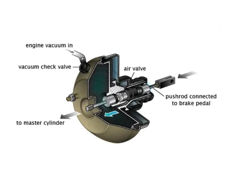
Brake boosters operate on the principle of force multiplication using either atmospheric pressure differentials or hydraulic pressure amplification. In vacuum brake boosters, the system creates a pressure differential across a large diaphragm, using atmospheric pressure to assist brake application. This design can multiply the driver’s input force by 5-7 times, making brake application much easier.
The physics behind force multiplication involves utilizing a large surface area (the booster diaphragm) to generate significant force from relatively small pressure differences. When the driver applies the brake pedal, a control valve opens to allow atmospheric pressure to act on one side of the diaphragm while maintaining vacuum on the other side. This pressure differential creates substantial force that assists brake application.
Hydraulic brake boosters use pressurized fluid to multiply force, typically operating at much higher pressures than vacuum systems. These systems can provide even greater force multiplication, making them suitable for heavier vehicles or applications requiring maximum braking power. The hydraulic advantage allows for very responsive brake feel and consistent performance.
Vacuum-Assisted vs. Hydraulic-Assisted Systems
Vacuum brake boosters represent the most common type, using engine manifold vacuum or a dedicated vacuum pump to create the low-pressure environment necessary for operation. These systems are cost-effective, reliable, and integrate well with traditional gasoline engines that naturally produce significant manifold vacuum during operation.
The vacuum system includes a large diaphragm chamber divided into two sections by a flexible diaphragm. During normal operation, both sides of the diaphragm are under vacuum. When the brake pedal is applied, a control valve allows atmospheric pressure to enter one side while maintaining vacuum on the other, creating the pressure differential that provides power assistance.
Hydraulic brake boosters, also known as hydro-boost systems, use pressurized hydraulic fluid from the power steering system to provide brake assistance. These systems are typically found on diesel vehicles, heavy-duty trucks, or vehicles where engine vacuum is insufficient for reliable brake booster operation. Hydraulic brake boosters integrate closely with power steering systems, requiring proper fluid maintenance for both systems.
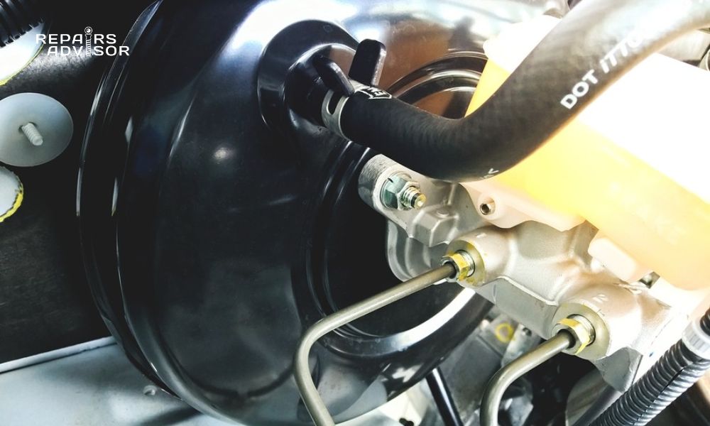
Integration with Master Cylinder Operation
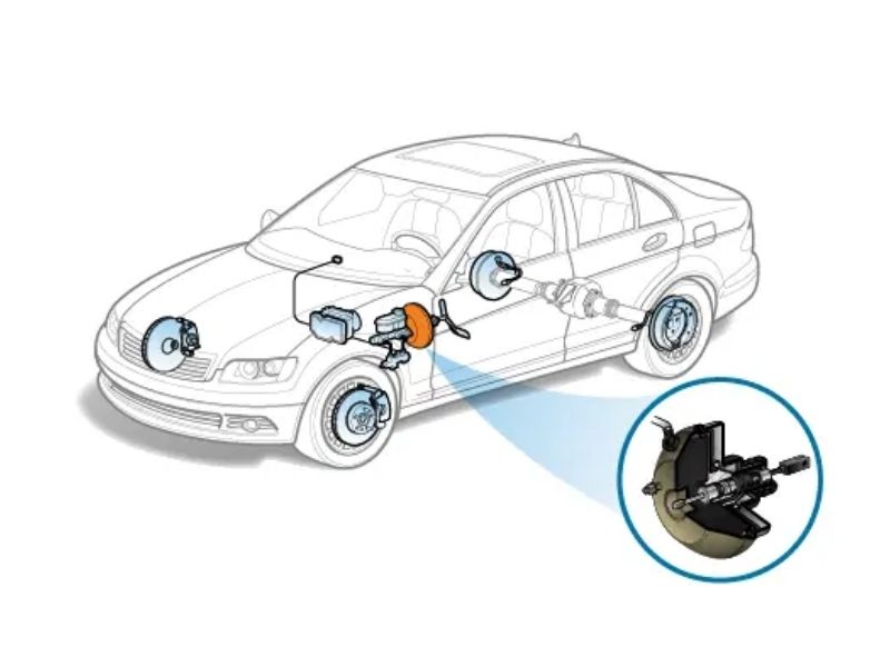
The brake booster mounts directly between the brake pedal and master cylinder, serving as an intermediate force multiplier in the brake system. The booster’s output pushes directly on the master cylinder’s primary piston, allowing the amplified force to generate higher hydraulic pressures in the brake lines.
Proper integration requires precise adjustment of the push rod that connects the booster to the master cylinder. This adjustment is critical for optimal brake feel and performance, as incorrect push rod length can cause dragging brakes, poor brake feel, or insufficient brake assist. The relationship between booster output and master cylinder input must be carefully calibrated during installation.
The integration also includes fail-safe features that maintain basic braking capability even if the power assist fails. The mechanical connection between the brake pedal and master cylinder ensures that drivers can still stop the vehicle manually, though with significantly increased effort. This fail-safe design is required by safety regulations and provides crucial backup capability.
Types of Brake Boosters
Vacuum Brake Boosters
Single Diaphragm Systems
Single diaphragm vacuum brake boosters use one large diaphragm to create the pressure differential necessary for power assistance. These systems are simpler in design and less expensive to manufacture, making them common on smaller passenger vehicles where space and cost considerations are important.
The single diaphragm design provides adequate force multiplication for most passenger car applications. The diaphragm diameter typically ranges from 8-11 inches, with larger diameters providing greater assistance. The system’s effectiveness depends on maintaining consistent vacuum levels and proper diaphragm sealing.
Single diaphragm boosters are generally reliable and easy to service, with fewer internal components than dual diaphragm designs. However, they provide less force multiplication than dual diaphragm systems and may not be suitable for heavier vehicles or applications requiring maximum braking assistance.
Dual Diaphragm Systems
Dual diaphragm vacuum brake boosters use two diaphragms working in tandem to provide greater force multiplication than single diaphragm designs. These systems are common on larger vehicles, trucks, and SUVs where higher braking forces are required. The dual diaphragm configuration can provide up to 50% more assistance than comparable single diaphragm systems.
The two diaphragms work together, with both contributing to the overall force output. This design allows for more compact packaging while still providing high force multiplication, making it suitable for vehicles with limited space in the engine compartment. The dual diaphragm configuration also provides some redundancy, as one diaphragm can continue to function even if the other fails.
Dual diaphragm systems require more complex internal valving and sealing systems, making them more expensive to manufacture and potentially more complex to service. However, the improved braking assistance they provide makes them essential for larger vehicles where adequate braking force would be difficult to achieve with single diaphragm designs.
Vacuum Source Requirements
Vacuum brake boosters require a consistent source of vacuum to operate effectively. Gasoline engines naturally produce manifold vacuum during operation, making them ideal for vacuum brake booster applications. The vacuum level must typically be at least 15-18 inches of mercury for proper booster operation, with higher vacuum levels providing better assistance.
Modern engines with advanced emissions controls and variable valve timing may produce less consistent vacuum than older designs, sometimes requiring auxiliary vacuum pumps to ensure reliable brake booster operation. These pumps, driven either mechanically or electrically, supplement engine vacuum when needed.
The vacuum system includes a check valve that prevents loss of vacuum when the engine is off or when manifold vacuum is low. This check valve maintains stored vacuum in the booster for several brake applications after engine shutdown, providing emergency braking capability. Regular check valve inspection and replacement is crucial for system reliability.
Hydraulic Brake Boosters
Power Steering Fluid Operation
Hydraulic brake boosters typically use the vehicle’s power steering system as a source of pressurized hydraulic fluid. The power steering pump provides pressurized fluid that operates both the steering assist and brake booster functions. This integration reduces system complexity and cost by utilizing existing hydraulic components.
The hydraulic brake booster contains internal valving that controls the flow of pressurized fluid to provide brake assistance. When the brake pedal is applied, a control valve directs pressurized fluid to assist brake application, while return fluid flows back to the power steering reservoir. This system can provide very high levels of brake assistance, making it suitable for heavy-duty applications.
Power steering fluid compatibility becomes critical in these systems, as the fluid must meet requirements for both steering and braking functions. Regular power steering system maintenance directly affects brake booster performance, making integrated system service important for optimal operation.
Hydro-Boost Systems
Hydro-boost brake systems represent a specialized type of hydraulic brake booster commonly found on diesel vehicles and heavy-duty trucks. These systems operate at higher pressures than typical power steering systems and provide very high levels of brake assistance suitable for heavy vehicle applications.
The hydro-boost system includes an accumulator that stores pressurized fluid for brake assistance even when the engine is not running. This accumulator provides several power-assisted brake applications after engine shutdown, similar to the stored vacuum in vacuum brake boosters. The accumulator also helps provide consistent brake feel by dampening pressure fluctuations.
Hydro-boost systems require specialized service procedures and equipment, as they operate at much higher pressures than vacuum systems. The high-pressure hydraulic components require careful handling and proper safety procedures during service to prevent injury from high-pressure fluid injection.
Electric-Hydraulic Boosters
Electric-hydraulic brake boosters represent the latest evolution in brake booster technology, using electric pumps to generate hydraulic pressure for brake assistance. These systems are increasingly common on hybrid and electric vehicles where engine vacuum is not available or inconsistent.
The electric-hydraulic system includes an electric pump, accumulator, and sophisticated electronic controls that provide very precise brake assistance. The system can vary the level of assistance based on driving conditions, brake pedal application speed, and integration with other vehicle systems like stability control and collision avoidance.
These systems offer advantages in packaging flexibility, precise control, and integration with advanced driver assistance systems. However, they require more complex electronic controls and diagnostic procedures, making service more challenging than traditional vacuum or hydraulic systems.
Electric Brake Boosters
Modern Electronic Systems
Electric brake boosters use electric motors to directly assist brake application, eliminating the need for vacuum or hydraulic assistance. These systems provide very precise control over brake assistance and can integrate seamlessly with electronic stability control and advanced driver assistance systems.
The electric booster includes sensors that monitor brake pedal position, application speed, and force, allowing the system to provide optimal assistance for different driving conditions. The electronic control unit can adjust assistance levels in real-time, providing better brake feel and more consistent performance than traditional systems.
Electric brake boosters also enable advanced features like brake-by-wire operation, where the brake pedal input is electronically interpreted and applied through electric actuators. This technology enables integration with autonomous emergency braking and other advanced safety systems.
Hybrid and Electric Vehicle Applications
Hybrid and electric vehicles present unique challenges for traditional brake boosters due to limited or inconsistent vacuum sources. Electric brake boosters provide ideal solutions for these applications, offering consistent brake assistance regardless of engine operation status.
The integration with regenerative braking systems requires sophisticated control algorithms to blend electric motor braking with friction brake application seamlessly. The electric brake booster can coordinate with the vehicle’s regenerative braking system to provide optimal energy recovery while maintaining proper brake feel and stopping performance.
These systems also support advanced energy management features, using the brake booster’s electric motor to harvest energy during braking or provide assistance using stored battery power. This integration improves overall vehicle efficiency while maintaining excellent braking performance.
Regenerative Braking Integration
Electric brake boosters in hybrid and electric vehicles must coordinate seamlessly with regenerative braking systems to provide optimal energy recovery and brake feel. The system determines how much braking force to apply through regenerative braking versus friction brakes based on battery state, vehicle speed, and driver input.
The coordination between electric brake boost and regenerative braking requires sophisticated control algorithms that operate in milliseconds to provide smooth, consistent brake feel. The system must transition seamlessly between regenerative and friction braking as conditions change, maintaining the driver’s expected brake response.
Advanced electric brake boosters can also provide brake assistance using energy recovered from regenerative braking, creating a closed-loop system that improves overall vehicle efficiency. This integration represents the future of brake system technology as vehicles become increasingly electrified.
Key Components of Brake Booster Systems
Vacuum Booster Components
Diaphragm Assembly
The diaphragm assembly forms the heart of a vacuum brake booster, consisting of a large flexible diaphragm that divides the booster housing into two chambers. The diaphragm material must be durable enough to withstand thousands of pressure cycles while maintaining flexibility and vacuum-tight sealing. Modern diaphragms typically use synthetic rubber compounds designed for long service life.
The diaphragm connects to a backing plate that distributes force evenly and provides a mounting point for the push rod assembly. The backing plate must be rigid enough to transfer force efficiently while being light enough to allow responsive brake feel. Some designs use multiple diaphragms to increase surface area and force multiplication.
Diaphragm failure typically occurs from material deterioration, contamination, or physical damage from debris. Signs of diaphragm failure include loss of brake assist, hissing sounds during brake application, and changes in engine idle when applying brakes. Regular inspection can identify early signs of diaphragm problems before complete failure occurs.
Check Valve Operation
The check valve prevents vacuum loss from the brake booster when engine vacuum is low or when the engine is not running. This one-way valve allows air to be evacuated from the booster during normal operation while preventing atmospheric pressure from entering when vacuum is lost. The check valve maintains stored vacuum for several brake applications after engine shutdown.
Check valve design varies but typically includes a spring-loaded ball or diaphragm that seals against atmospheric pressure while allowing vacuum flow. The valve must respond quickly to pressure changes while maintaining reliable sealing over thousands of cycles. Some designs include additional features like vacuum reserve tanks to extend brake assist availability.
Check valve failure can cause loss of stored vacuum, resulting in hard brake pedal feel and loss of power assist. Testing check valve operation involves monitoring vacuum levels during various engine operating conditions and verifying that vacuum is maintained when the engine is shut off. A failed check valve typically requires replacement of the entire vacuum hose assembly.
Push Rod Mechanism
The push rod mechanism transfers the amplified force from the brake booster diaphragm to the master cylinder piston. This mechanism includes the push rod, connecting hardware, and adjustment provisions that ensure proper force transfer and brake system operation. Push rod adjustment is critical for optimal brake feel and performance.
The push rod design must provide reliable force transfer while accommodating thermal expansion, vibration, and normal wear. Some designs include swivel joints or flexible connections to accommodate misalignment between the booster and master cylinder. The push rod typically connects to the diaphragm backing plate through a clevis or ball joint arrangement.
Proper push rod adjustment ensures that the master cylinder piston returns fully when brakes are released while providing immediate response when brakes are applied. Incorrect adjustment can cause brake drag, poor brake feel, or inadequate brake assist. Professional adjustment typically requires special gauges and procedures specific to each vehicle model.
Vacuum Chamber Design
The vacuum chamber design determines the brake booster’s effectiveness and reliability. The chamber must maintain vacuum under various operating conditions while providing smooth, responsive brake assistance. Chamber size directly affects the amount of force multiplication available, with larger chambers providing greater assistance.
Internal chamber design includes provisions for mounting the diaphragm assembly, control valves, and push rod mechanism. The chamber walls must be strong enough to withstand atmospheric pressure differentials while being light enough for practical vehicle installation. Some designs include reinforcement ribs or thicker wall sections in high-stress areas.
Vacuum chamber integrity is crucial for proper brake booster operation. Cracks, corrosion, or other damage can cause vacuum loss and brake assist failure. Regular inspection of the vacuum chamber and associated components helps identify potential problems before they affect brake system performance.
Hydraulic Booster Components
Accumulator Function
The hydraulic accumulator stores pressurized brake fluid to provide brake assistance even when the hydraulic pump is not operating. This component is essential for maintaining brake assist during engine-off conditions and provides pressure stability during brake application. The accumulator typically uses a nitrogen-charged diaphragm or piston to maintain pressure.
Accumulator operation depends on maintaining proper nitrogen precharge pressure and fluid sealing. The nitrogen charge provides the spring force necessary to maintain hydraulic pressure, while the fluid side provides the working pressure for brake assistance. Proper accumulator function requires periodic pressure testing and recharging as needed.
Accumulator failure can result in loss of brake assist, particularly during engine-off braking or rapid brake applications. Signs of accumulator problems include hard brake pedal feel, pump motor cycling during brake application, and loss of brake assist after engine shutdown. Professional service typically requires specialized equipment for pressure testing and nitrogen charging.
Pressure Pump Operation
The hydraulic pressure pump provides the high-pressure fluid necessary for brake booster operation. This pump may be driven mechanically by the engine or electrically by a dedicated motor. Electric pumps are more common in modern systems due to their precise control capabilities and independence from engine operation.
Pump design varies but typically includes high-pressure pistons or gear mechanisms capable of generating 1,500-3,000 PSI working pressure. The pump must provide adequate flow and pressure for brake assist while maintaining quiet operation and long service life. Some systems include pressure switches or sensors that control pump operation based on system demands.
Pump failure can cause complete loss of brake assist, though manual braking capability typically remains. Symptoms include lack of brake assist, unusual noises during brake application, and pump motor running continuously. Professional diagnosis typically requires pressure testing equipment and knowledge of system specifications.
Control Valve Assembly
The control valve assembly regulates hydraulic pressure to provide appropriate brake assistance based on driver input. This complex valve system must respond quickly to brake pedal movement while providing smooth, predictable brake feel. The valve design typically includes multiple chambers and spring-loaded components.
Control valve operation involves detecting brake pedal movement and applying proportional hydraulic assistance. The valve must provide immediate response for emergency braking while preventing excessive assistance during light brake applications. Some designs include electronic controls that can modify valve operation based on driving conditions.
Control valve problems can cause erratic brake feel, excessive or insufficient brake assist, or complete loss of power assistance. Diagnosis typically requires specialized pressure testing equipment and understanding of valve operation principles. Control valve repair usually requires replacement of the entire brake booster assembly.
Fluid Reservoir Integration
Hydraulic brake boosters typically share fluid reservoirs with the power steering system, requiring careful attention to fluid level, condition, and compatibility. The shared reservoir design reduces system complexity but makes fluid maintenance critical for both steering and braking functions.
Reservoir design must accommodate the fluid volume changes that occur during brake booster operation while maintaining proper fluid levels for power steering operation. Some systems include separate compartments or level sensors to monitor fluid levels independently for each system.
Fluid contamination or low levels can affect both brake booster and power steering operation. Regular fluid service helps prevent problems and ensures optimal performance of both systems. Power steering system maintenance directly impacts brake booster performance in these integrated systems.
Master Cylinder Integration
Mounting Configuration
Brake booster mounting configuration must provide rigid support while allowing for thermal expansion and vibration isolation. The booster typically mounts to the firewall or bulkhead with the master cylinder mounted directly to the booster output. This configuration ensures proper force transfer and maintains brake system alignment.
Mounting hardware must be strong enough to handle the forces generated during brake application while providing vibration isolation to prevent noise and component fatigue. Some designs include rubber isolators or flexible mounting provisions to accommodate thermal expansion and reduce noise transmission.
Proper mounting alignment is crucial for optimal brake system operation and component life. Misalignment can cause binding, uneven wear, or poor brake feel. Professional installation typically requires torque specifications and alignment procedures specific to each vehicle model.
Push Rod Adjustment
Push rod adjustment between the brake booster and master cylinder is critical for proper brake system operation. The adjustment determines the relationship between brake pedal travel and master cylinder operation, affecting brake feel, response, and component life. Incorrect adjustment can cause serious brake system problems.
The adjustment procedure typically involves measuring push rod length with special gauges or templates provided by the manufacturer. Some systems include adjustable push rods with locknut provisions, while others require selection of different length push rods to achieve proper adjustment.
Push rod adjustment affects brake pedal free play, master cylinder return characteristics, and brake assist effectiveness. Too much adjustment can cause brake drag and premature component wear, while insufficient adjustment can cause poor brake feel and delayed response. Professional adjustment ensures optimal brake system performance and safety.
Brake Fluid Compatibility
Brake fluid compatibility between the master cylinder and brake booster is essential for proper system operation and component life. The fluid must meet specifications for both hydraulic brake operation and brake booster internal components. Incompatible fluids can cause seal deterioration and system failure.
Most brake systems use DOT 3 or DOT 4 brake fluid, but some high-performance or specialized applications may require different fluid types. The brake booster internal seals and components must be compatible with the specified fluid type to prevent deterioration and failure.
Regular brake fluid service helps maintain system performance and prevent contamination problems. The brake fluid should be replaced according to manufacturer recommendations, typically every 2-3 years, to prevent moisture absorption and contamination that can affect both brake and booster operation.
Signs Your Brake Booster Is Failing
Increased Brake Pedal Effort
The most obvious sign of brake booster failure is increased effort required to apply the brakes. Drivers may notice that they need to push the brake pedal much harder than normal to achieve the same stopping power. This change can be gradual or sudden, depending on the type of failure occurring within the brake booster system.
Increased pedal effort indicates loss of power assistance, which can make emergency braking significantly more difficult and potentially dangerous. The brake system typically retains basic stopping capability even with booster failure, but the effort required may be 5-7 times higher than normal. This condition requires immediate professional attention to restore proper brake operation.
The increased effort may be more noticeable during certain driving conditions, such as stop-and-go traffic or when parking. Drivers should be particularly aware of changes in brake feel and seek professional diagnosis whenever brake pedal effort increases noticeably. Early detection can prevent complete power assist failure and maintain vehicle safety.
Spongy or Soft Brake Pedal Feel
A spongy or soft brake pedal feel can indicate internal problems within the brake booster, particularly in hydraulic boost systems. This condition occurs when air enters the hydraulic system or when internal seals begin to fail, allowing fluid bypassing that reduces system efficiency.
The spongy feel may be accompanied by increased pedal travel or a pedal that gradually sinks to the floor when steady pressure is applied. These symptoms indicate serious brake system problems that require immediate professional attention to prevent brake failure.
In vacuum brake boosters, spongy pedal feel may indicate diaphragm failure or vacuum leaks that affect system operation. The problem may be intermittent initially but typically worsens over time as the underlying condition deteriorates. Professional diagnosis can identify the specific cause and recommend appropriate repairs.
Brake Pedal Sinking to Floor
A brake pedal that sinks to the floor when steady pressure is applied indicates serious brake system problems that may involve the brake booster, master cylinder, or hydraulic system. This condition represents a significant safety hazard and requires immediate professional attention.
In hydraulic brake boosters, internal seal failure can allow pressurized fluid to bypass, causing the pedal to sink gradually. The condition may be more noticeable when the vehicle is stationary with the engine running, as the booster continues to operate and internal leakage becomes apparent.
Brake pedal sinking can also indicate master cylinder problems or external hydraulic leaks in the brake system. Professional diagnosis with pressure testing equipment is necessary to determine the exact cause and ensure proper repair. Driving should be avoided until the problem is corrected by qualified technicians.
Hissing Sounds During Braking
Hissing sounds during brake application often indicate vacuum leaks in vacuum brake booster systems. The sound occurs when atmospheric air enters the vacuum chamber through failed seals, cracked housing, or damaged vacuum lines. This condition causes loss of brake assist and requires prompt repair.
The hissing sound may be most noticeable when the brake pedal is applied with the engine running. The sound indicates that vacuum is being lost, which reduces or eliminates the power assistance provided by the brake booster. Continuing to drive with this condition is unsafe due to increased brake pedal effort.
Vacuum leaks can also affect engine operation, causing rough idle or changes in engine speed when brakes are applied. These symptoms help confirm brake booster problems and distinguish them from other brake system issues. Professional diagnosis can locate the exact source of vacuum leaks and recommend appropriate repairs.
Engine Performance Changes
Engine performance changes during brake application can indicate vacuum brake booster problems affecting engine operation. When the brake booster has internal vacuum leaks, applying the brakes can cause changes in engine idle speed, rough running, or stalling, particularly in vehicles with smaller engines.
The engine changes occur because vacuum leaks in the brake booster create additional load on the engine’s vacuum system, affecting other vacuum-operated components like emission controls and idle air control systems. These symptoms are most noticeable at idle when engine vacuum production is lower.
Modern engines with electronic controls may compensate for small vacuum leaks automatically, making engine performance changes less noticeable. However, larger leaks or sudden failures can still cause noticeable engine performance problems that help identify brake booster issues.
Brake Warning Light Activation
Modern vehicles with electronic brake systems may illuminate brake warning lights when brake booster problems are detected. These warning systems can monitor vacuum levels, hydraulic pressures, or electric brake booster operation and alert drivers to problems before complete failure occurs.
The brake warning light activation may be accompanied by reduced brake assist or changes in brake pedal feel. Some systems provide specific diagnostic codes that help identify the exact nature of the brake booster problem, making professional diagnosis more efficient.
Electronic brake monitoring systems vary by manufacturer and model year, so professional diagnosis with appropriate scan tools is necessary to interpret warning light activation properly. The warning lights should never be ignored, as they indicate potential safety problems requiring immediate attention.
Diagnosing Brake Booster Problems
Visual Inspection Procedures
Visual inspection provides the first step in brake booster diagnosis, allowing technicians to identify obvious problems like physical damage, vacuum leaks, or hydraulic fluid leaks. The inspection should include the brake booster housing, vacuum lines, hydraulic connections, and mounting hardware.
Common visual inspection points include checking for cracks in the brake booster housing, damaged or disconnected vacuum lines, hydraulic fluid leaks around connections, and proper mounting hardware torque. The inspection should also include checking the condition of related components like the master cylinder and vacuum check valve.
Physical damage to the brake booster housing can cause vacuum or hydraulic leaks that affect system operation. Corrosion, impact damage, or manufacturing defects can create cracks or holes that compromise brake booster function. Professional inspection with proper lighting and access equipment ensures thorough evaluation of all components.
Vacuum Testing Methods
Vacuum testing provides definitive diagnosis of vacuum brake booster problems by measuring actual vacuum levels and system performance. The testing typically involves connecting a vacuum gauge to the brake booster and monitoring vacuum under various operating conditions.
Basic vacuum testing includes checking engine manifold vacuum, brake booster stored vacuum, and vacuum retention when the engine is shut off. The tests help identify problems with vacuum production, check valve operation, or internal booster leaks that affect performance.
Advanced vacuum testing may include leak-down tests that measure how quickly vacuum is lost from the brake booster system. These tests can identify small leaks that might not be apparent during basic testing but still affect brake booster operation. Professional vacuum testing equipment ensures accurate diagnosis of vacuum system problems.
Hydraulic Pressure Testing
Hydraulic brake boosters require pressure testing to verify proper pump operation, accumulator function, and system performance. The testing involves connecting pressure gauges to the hydraulic system and monitoring pressures during various operating conditions.
Pressure testing typically includes checking pump output pressure, accumulator precharge pressure, and system pressure during brake application. The tests help identify problems with pump operation, accumulator function, or internal leaks that affect brake booster performance.
Professional hydraulic testing requires specialized high-pressure equipment and safety procedures due to the high pressures involved in hydraulic brake booster systems. The testing must be performed by qualified technicians with appropriate equipment to ensure accurate diagnosis and prevent injury.
Check Valve Function Testing
Check valve testing verifies proper operation of the vacuum retention system in vacuum brake boosters. The testing involves monitoring vacuum levels before and after engine shutdown to verify that the check valve maintains stored vacuum for brake assist.
Proper check valve function allows several brake applications with power assist after the engine is shut off. The check valve should maintain vacuum for at least 15-20 minutes after engine shutdown and provide 2-3 power-assisted brake applications. Failure to maintain vacuum indicates check valve problems.
Check valve testing can be performed with basic vacuum testing equipment by monitoring vacuum retention over time. Some check valves include built-in vacuum reservoirs that extend brake assist availability after engine shutdown. Professional testing verifies proper operation of all vacuum retention components.
Master Cylinder Push Rod Adjustment
Push rod adjustment verification ensures proper mechanical connection between the brake booster and master cylinder. Incorrect adjustment can cause brake problems that may be mistakenly attributed to brake booster failure, making proper adjustment verification important for accurate diagnosis.
Push rod adjustment testing typically involves measuring the extension of the push rod from the brake booster and comparing it to manufacturer specifications. Special gauges or templates may be required to ensure accurate measurement and proper adjustment.
Incorrect push rod adjustment can cause brake drag, poor brake feel, or inadequate brake assist. The adjustment affects brake pedal free play and master cylinder operation, making proper adjustment critical for optimal brake system performance and component life.
Common Brake Booster Failure Modes
Diaphragm Rupture and Leakage
Diaphragm rupture represents one of the most common failure modes in vacuum brake boosters, typically resulting from material deterioration, contamination, or physical stress. When the diaphragm fails, vacuum is lost and brake assist is eliminated, requiring significantly increased pedal effort for braking.
Diaphragm failure often occurs gradually, with small tears or pin holes developing before complete rupture. Early stages may cause intermittent loss of brake assist or hissing sounds during brake application. Complete diaphragm failure results in immediate and total loss of power assistance.
The diaphragm material can deteriorate from exposure to engine oils, brake fluid, or other contaminants that enter the vacuum system. Age-related deterioration is also common, particularly in vehicles with high mileage or those exposed to extreme temperature variations. Regular inspection can identify early signs of diaphragm problems.
Check Valve Malfunction
Check valve malfunction prevents proper vacuum retention in the brake booster system, causing loss of stored vacuum and reduced brake assist availability. The check valve may fail to seal properly, allowing atmospheric pressure to enter the vacuum system, or it may stick closed, preventing vacuum evacuation.
Failed check valves typically cause rapid loss of vacuum when the engine is shut off, eliminating power-assisted brake applications during engine-off conditions. The condition may also cause hard brake pedal feel during engine operation if the check valve fails to allow proper vacuum flow to the brake booster.
Check valve problems can be intermittent, causing inconsistent brake assist performance that may be difficult to diagnose. Environmental factors like temperature changes or contamination can affect check valve operation, making thorough testing important for accurate diagnosis.
Vacuum Pump Failure
Modern vehicles with limited engine vacuum may use auxiliary vacuum pumps to ensure adequate brake booster operation. These pumps can fail mechanically or electrically, causing loss of vacuum and brake assist. Pump failure is particularly common on diesel vehicles and those with turbocharging or other factors that reduce engine vacuum.
Electric vacuum pump failure may be indicated by pump motor not running, unusual noises, or insufficient vacuum production. The pumps typically include pressure switches or sensors that control operation based on vacuum levels, and these components can also fail and affect pump operation.
Mechanical vacuum pump failure may cause unusual noises, reduced vacuum production, or oil leaks from pump mounting areas. These pumps are typically driven by the engine and require regular maintenance to ensure reliable operation and prevent premature failure.
Hydraulic Accumulator Problems
Hydraulic accumulator problems in hydro-boost systems can cause loss of stored pressure and reduced brake assist availability. The accumulator typically uses a nitrogen-charged diaphragm or piston to maintain pressure, and failure of these components affects system performance.
Accumulator failure may be indicated by rapid loss of brake assist after engine shutdown, pump motor cycling during brake application, or hard brake pedal feel. The nitrogen charge in the accumulator can leak slowly over time, requiring periodic recharging to maintain proper operation.
Internal accumulator problems can include diaphragm failure, seal deterioration, or contamination that affects pressure retention. Professional diagnosis with pressure testing equipment is necessary to verify accumulator function and determine repair requirements.
Internal Seal Deterioration
Internal seal deterioration affects both vacuum and hydraulic brake boosters, causing gradual loss of performance and eventual system failure. Seals can deteriorate from age, contamination, or exposure to incompatible fluids, resulting in internal leakage that reduces brake assist effectiveness.
In vacuum brake boosters, seal deterioration allows atmospheric air to enter the vacuum chamber, reducing the pressure differential available for brake assistance. The deterioration may be gradual, causing slowly increasing brake pedal effort over time, making the problem difficult to notice until significant performance loss occurs.
Hydraulic brake booster seal deterioration allows pressurized fluid to bypass internally, reducing system efficiency and causing spongy brake pedal feel. The condition may worsen under high-pressure conditions or during extended brake applications, making diagnosis challenging without proper pressure testing equipment.
Brake Booster Testing Procedures
Engine-Off Brake Pedal Test
The engine-off brake pedal test provides a basic assessment of brake booster function by evaluating stored vacuum or pressure availability. With the engine off, apply the brake pedal several times to deplete any stored assist, then start the engine while maintaining light pressure on the brake pedal.
A properly functioning brake booster should cause the pedal to drop slightly when the engine starts, indicating that power assist has been restored. If the pedal does not drop or drops only slightly, the brake booster may have internal problems or insufficient vacuum/pressure source.
This test provides a quick initial assessment but should be followed by more comprehensive testing for accurate diagnosis. The test results can help determine whether problems lie within the brake booster itself or in the vacuum/pressure source systems.
Engine-Running Vacuum Test
Engine-running vacuum testing measures actual vacuum levels at the brake booster during various operating conditions. Connect a vacuum gauge to the brake booster vacuum line and monitor readings with the engine at idle, under load, and during brake application.
Proper vacuum levels typically range from 15-22 inches of mercury at idle, depending on engine design and operating conditions. Lower vacuum levels may indicate engine problems, vacuum leaks, or issues with vacuum production that affect brake booster operation.
During brake application with the engine running, vacuum levels should remain relatively stable or drop only slightly. Rapid vacuum loss during brake application indicates internal brake booster leaks that require repair or replacement.
Brake Pedal Hold Test
The brake pedal hold test evaluates brake booster performance under sustained load conditions. With the engine running, apply firm pressure to the brake pedal and hold for 30-60 seconds while monitoring pedal feel and position.
A properly functioning brake booster should maintain consistent pedal feel and position during the hold test. If the pedal gradually sinks or becomes harder to hold, internal problems may exist within the brake booster or master cylinder systems.
This test can reveal problems that may not be apparent during normal driving conditions, particularly internal leakage that becomes evident under sustained pressure. Professional interpretation of test results helps distinguish between brake booster and master cylinder problems.
Check Valve Isolation Test
Check valve isolation testing verifies proper vacuum retention in the brake booster system. Disconnect the vacuum line between the engine and brake booster, then monitor vacuum retention in the brake booster with the engine off.
A properly functioning check valve should maintain vacuum in the brake booster for at least 15-20 minutes after disconnection. Rapid vacuum loss indicates check valve failure or internal brake booster leaks that require repair.
The test can be enhanced by applying light brake pressure while monitoring vacuum retention. Vacuum should remain stable during light brake applications, with significant vacuum loss only occurring during heavy brake applications that consume stored vacuum.
Professional Diagnostic Equipment
Professional brake booster diagnosis often requires specialized equipment for accurate testing and evaluation. Vacuum testing equipment, hydraulic pressure gauges, and electronic diagnostic tools provide comprehensive assessment of brake booster systems.
Modern vehicles with electronic brake systems may require scan tools to access brake system diagnostic codes and monitor system operation parameters. These tools can provide valuable information about brake booster performance and help identify specific problems within complex brake systems.
Professional equipment also includes safety devices and procedures necessary for working with high-pressure hydraulic systems or vacuum systems. Proper equipment and training ensure accurate diagnosis while maintaining technician safety during testing procedures.
Maintenance and Service Requirements
Regular Inspection Intervals
Brake booster maintenance should follow manufacturer recommendations, typically including inspection during regular brake service intervals. Most manufacturers recommend brake system inspection every 12,000-15,000 miles or annually, whichever comes first.
Visual inspection should include checking for vacuum leaks, hydraulic fluid leaks, and physical damage to the brake booster housing and related components. Early detection of problems can prevent complete system failure and maintain vehicle safety.
The inspection should also include testing brake pedal feel and operation to identify changes that might indicate developing brake booster problems. Professional technicians can perform more comprehensive testing during regular service intervals to ensure optimal system performance.
Vacuum System Maintenance
Vacuum system maintenance includes regular inspection and replacement of vacuum lines, check valves, and related components. Vacuum lines can deteriorate from heat, oil exposure, or age, causing leaks that affect brake booster operation.
Check valve replacement should follow manufacturer recommendations or be performed when testing indicates improper function. Some vehicles include vacuum reservoirs or auxiliary components that require periodic inspection and service.
Engine maintenance also affects vacuum brake booster operation, as engine problems can reduce vacuum production and affect brake assist availability. Regular engine maintenance helps ensure adequate vacuum for proper brake booster operation.
Hydraulic Fluid Service
Hydraulic brake boosters require regular fluid service to maintain proper operation and prevent contamination problems. The hydraulic fluid typically shares a reservoir with the power steering system, making integrated system maintenance important for both functions.
Fluid replacement intervals vary by manufacturer but typically range from 30,000-60,000 miles or every 3-5 years. Contaminated or deteriorated fluid can cause internal component damage and affect brake booster performance.
Proper fluid type is critical for hydraulic brake booster systems, as the fluid must meet specifications for both brake assist and power steering operation. Using incorrect fluid types can cause seal deterioration and system failure.
Filter Replacement Requirements
Some hydraulic brake booster systems include filters that require periodic replacement to prevent contamination and maintain proper operation. These filters typically protect sensitive internal components from debris that could cause valve sticking or seal damage.
Filter replacement intervals vary by system design and operating conditions but typically range from 30,000-60,000 miles. Contaminated filters can restrict fluid flow and affect brake booster performance, making regular replacement important for system reliability.
Professional service typically includes filter inspection and replacement as part of comprehensive hydraulic system maintenance. Proper disposal of used filters and fluids follows environmental regulations and best practices.
Environmental Protection Measures
Brake booster systems require protection from environmental contamination that can affect performance and reliability. Road salt, moisture, and debris can cause corrosion or damage to external components, requiring preventive maintenance measures.
Regular cleaning of brake booster components and protection of electrical connections helps prevent corrosion and ensures reliable operation. Some systems include protective covers or shields that require periodic inspection and maintenance.
Environmental factors like extreme temperatures, high humidity, or corrosive conditions may require more frequent inspection and maintenance to prevent premature component failure. Professional assessment of environmental factors helps determine appropriate maintenance intervals.
Brake Booster Replacement Considerations
When Replacement Is Necessary
Brake booster replacement becomes necessary when internal failures cannot be repaired or when the cost of repair exceeds replacement costs. Common conditions requiring replacement include diaphragm failure, internal seal deterioration, or housing damage that compromises system integrity.
Safety considerations make brake booster replacement urgent when power assist is lost or significantly reduced. Continuing to drive with failed brake boost creates safety hazards due to increased brake pedal effort required for stopping.
Professional assessment helps determine whether repair or replacement is most appropriate based on the specific failure mode, vehicle age, and cost considerations. Some brake booster problems can be corrected with component replacement, while others require complete unit replacement.
OEM vs. Aftermarket Options
Original Equipment Manufacturer (OEM) brake boosters provide exact specifications and performance characteristics as the original installation. OEM components typically offer the best fit, performance, and reliability but may be more expensive than aftermarket alternatives.
Aftermarket brake boosters can provide cost savings while maintaining adequate performance for most applications. Quality aftermarket manufacturers often provide components that meet or exceed OEM specifications, though careful selection is important to ensure proper fit and performance.
Professional installation services can help evaluate OEM versus aftermarket options based on vehicle requirements, budget considerations, and expected service life. Warranty coverage and support also differ between OEM and aftermarket components.
Installation Complexity and Requirements
Brake booster installation complexity varies by vehicle design and brake booster type. Vacuum brake boosters typically require simpler installation procedures than hydraulic systems, which may require specialized tools and pressure bleeding procedures.
Installation typically includes removing the master cylinder, disconnecting vacuum or hydraulic lines, and unbolting the brake booster from the firewall. Proper installation requires torque specifications, push rod adjustment, and system bleeding procedures specific to each vehicle model.
Professional installation ensures proper adjustment and system bleeding, which are critical for safe brake operation. Improper installation can cause brake problems, component damage, or safety hazards that require correction by qualified technicians.
Calibration and Adjustment Procedures
Modern brake boosters may require calibration or adjustment procedures after installation to ensure optimal performance and integration with electronic brake systems. These procedures typically require manufacturer-specific diagnostic equipment and software.
Push rod adjustment between the brake booster and master cylinder is critical for proper operation and must be performed according to manufacturer specifications. Incorrect adjustment can cause brake drag, poor brake feel, or inadequate brake assist.
Electronic brake boosters may require programming or calibration procedures to integrate properly with the vehicle’s electronic systems. These procedures ensure proper communication between the brake booster and other safety systems like ABS and stability control.
System Bleeding Requirements
Brake system bleeding after brake booster replacement ensures proper operation and removes air that may have entered the hydraulic system during installation. The bleeding procedure varies by brake system design and may require special equipment or techniques.
Proper bleeding is essential for safe brake operation and must be performed according to manufacturer procedures to ensure complete air removal. Some systems require pressure bleeding or scan tool-controlled bleeding procedures for proper air removal.
Professional bleeding equipment and procedures ensure thorough air removal and proper brake system operation after brake booster replacement. Incomplete bleeding can cause spongy brake feel, reduced stopping power, or brake system failure.
Integration with Modern Brake Systems
ABS System Coordination
Modern brake boosters must coordinate seamlessly with Anti-lock Braking System (ABS) operation to provide optimal braking performance. The brake booster provides the basic power assist while ABS modulates individual wheel pressures to prevent wheel lockup during emergency braking.
The integration requires precise brake pressure control and rapid response to ABS control module commands. Brake booster problems can affect ABS operation by altering the baseline brake pressure or response characteristics that ABS systems depend on for proper operation.
Professional diagnosis of brake problems in ABS-equipped vehicles requires understanding the interaction between brake booster and ABS systems. Problems in one system can affect the other, making comprehensive diagnosis important for accurate problem identification and repair.
Electronic Stability Control Integration
Electronic Stability Control (ESC) systems use brake booster components to apply individual wheel brakes automatically for vehicle stability control. The brake booster must provide adequate pressure and response for ESC operation while maintaining normal brake feel for driver-applied braking.
ESC integration requires sophisticated control algorithms that coordinate brake booster operation with stability sensors and electronic controls. The system must distinguish between driver-applied braking and automatic ESC intervention while providing appropriate brake assist for each condition.
Brake booster problems can affect ESC operation by reducing available brake pressure or altering system response characteristics. Professional diagnosis requires understanding ESC operation and its dependence on brake booster performance for proper vehicle stability control.
Brake Assist System Operation
Brake Assist systems detect emergency braking situations and automatically apply maximum brake force to help drivers achieve optimal stopping performance. These systems depend on brake booster operation to provide the high brake pressures necessary for maximum stopping power.
The integration between brake assist and brake booster requires rapid response and high force capability to provide effective emergency braking assistance. Brake booster problems can reduce brake assist effectiveness and compromise emergency braking performance.
Modern brake assist systems may include electronic controls that modify brake booster operation based on driving conditions and emergency detection algorithms. Professional service requires understanding these complex interactions and their effect on overall brake system performance.
Hybrid Vehicle Considerations
Hybrid vehicles present unique challenges for brake booster operation due to regenerative braking systems that must coordinate with friction brakes. The brake booster must provide consistent brake feel while the vehicle transitions between regenerative and friction braking modes.
Electric and hydraulic brake boosters are increasingly common on hybrid vehicles because they provide precise control and independence from engine vacuum. These systems can coordinate with regenerative braking to provide optimal energy recovery while maintaining proper brake feel.
Professional service of hybrid vehicle brake systems requires understanding the interaction between brake booster, regenerative braking, and vehicle energy management systems. Specialized diagnostic equipment and training are necessary for proper diagnosis and repair of these complex integrated systems.
Advanced Driver Assistance Systems
Advanced Driver Assistance Systems (ADAS) increasingly rely on brake booster systems for automatic emergency braking, adaptive cruise control, and collision avoidance functions. These systems require very precise brake pressure control and rapid response that depends on brake booster performance.
The integration with ADAS requires brake boosters that can provide both driver-controlled braking and automatic system-controlled braking seamlessly. Electronic brake boosters are particularly suited for these applications due to their precise control capabilities and fast response times.
Professional service of ADAS-equipped vehicles requires understanding the dependence of safety systems on brake booster operation. Brake booster problems can affect multiple vehicle safety systems, making proper diagnosis and repair critical for vehicle safety and ADAS operation.
Troubleshooting Common Issues
Hard Brake Pedal Diagnosis
Hard brake pedal diagnosis begins with determining whether the problem lies within the brake booster, vacuum/pressure source, or related components. A hard brake pedal typically indicates loss of power assist from brake booster failure, vacuum loss, or hydraulic pressure problems.
Initial diagnosis includes checking vacuum levels at the brake booster, testing check valve operation, and verifying proper brake booster function using established test procedures. The diagnosis should also include inspection of vacuum lines, electrical connections, and related components.
Professional diagnosis may require pressure testing, vacuum testing, or electronic system diagnosis depending on the type of brake booster and vehicle systems involved. Accurate diagnosis ensures proper repair and prevents misidentification of problems that could lead to safety issues.
Vacuum Leak Detection
Vacuum leak detection requires systematic testing of all vacuum system components to identify the source of leaks affecting brake booster operation. Common leak sources include vacuum lines, check valves, brake booster housing, and connections between components.
Vacuum leak detection methods include smoke testing, vacuum gauge monitoring, and audible inspection for hissing sounds that indicate air entering the vacuum system. Professional detection equipment can locate small leaks that might not be apparent through basic testing methods.
Vacuum leaks can affect both brake booster operation and engine performance, making comprehensive diagnosis important for identifying all affected systems. Proper repair of vacuum leaks ensures optimal brake booster operation and prevents related engine performance problems.
Hydraulic System Problems
Hydraulic brake booster problems require specialized diagnosis due to the high pressures and complex components involved. Common problems include pump failure, accumulator problems, and internal leakage that affects system pressure and brake assist performance.
Diagnosis typically requires pressure testing equipment capable of measuring the high pressures used in hydraulic brake booster systems. Professional safety procedures are essential due to the high-pressure hydraulic systems that can cause serious injury if handled improperly.
Hydraulic system problems can also affect power steering operation in vehicles with shared fluid systems, making comprehensive diagnosis important for identifying all affected systems and ensuring proper repair of integrated hydraulic systems.
Intermittent Power Assist Loss
Intermittent power assist loss can be challenging to diagnose because the problem may not be present during testing. Common causes include marginal vacuum levels, intermittent check valve problems, or early-stage component failures that occur only under specific conditions.
Diagnosis may require extended testing under various operating conditions to reproduce the intermittent condition. Professional diagnostic equipment can monitor system operation over time to identify patterns or conditions that trigger the intermittent problem.
Temperature changes, altitude variations, or specific driving conditions may trigger intermittent problems, making thorough testing and customer interview important for accurate diagnosis. Professional experience helps identify likely causes and appropriate testing procedures.
Noise and Vibration Issues
Brake booster noise and vibration problems can indicate internal component damage, improper installation, or interaction with other vehicle systems. Common noise sources include internal component failure, vacuum leaks, or pump motor problems in hydraulic systems.
Diagnosis requires identifying the specific type of noise, when it occurs, and what conditions trigger the problem. Professional diagnostic techniques include using listening devices, vibration analysis, and systematic component testing to isolate noise sources.
Some brake booster noises may be normal operation sounds that become more noticeable due to changes in other vehicle systems or component wear. Professional assessment helps distinguish between normal operation sounds and abnormal noises that indicate problems requiring repair.
Safety Considerations and Best Practices
Safe Operating Procedures
Safe brake booster operation requires understanding system limitations and proper driving techniques for both normal and emergency conditions. Drivers should be aware that brake booster failure significantly increases brake pedal effort required for stopping and adjust driving accordingly.
Regular brake system inspection and maintenance helps prevent brake booster problems and ensures optimal performance when needed. Professional inspection can identify potential problems before they affect vehicle safety or leave drivers stranded with brake assist failure.
Understanding proper emergency braking techniques with and without power assist helps drivers respond appropriately to brake system problems. Professional training or educational resources can help drivers understand brake system operation and proper response to brake problems.
Emergency Braking Without Power Assist
Emergency braking without power assist requires significantly more pedal force than power-assisted braking. Drivers must be prepared to apply much greater force to achieve adequate stopping power when brake booster assistance is lost.
The brake system typically retains basic stopping capability even with complete power assist failure, but stopping distances may increase due to the difficulty of applying maximum brake force manually. Drivers should maintain greater following distances when brake assist problems are suspected.
Professional emergency response training can help drivers understand proper techniques for emergency braking without power assist. Understanding brake system capabilities and limitations helps drivers respond appropriately to brake system failures and maintain vehicle control.
Professional Service Requirements
Brake booster service requires specialized knowledge, equipment, and safety procedures that are typically available only at qualified service facilities. Professional service ensures proper diagnosis, repair, and testing that maintains vehicle safety and brake system performance.
The complexity of modern brake systems with electronic controls, integration with safety systems, and high-pressure hydraulic components makes professional service essential for most brake booster problems. Attempting repairs without proper training and equipment can create safety hazards.
Professional service also includes warranty coverage and liability protection that may not be available with non-professional repairs. The safety-critical nature of brake systems makes professional service particularly important for brake booster problems that affect vehicle stopping capability.
System Limitations and Driving Adjustments
Brake booster systems have limitations that drivers should understand for optimal safety and performance. Environmental conditions, system age, and maintenance condition all affect brake booster performance and may require driving adjustments to maintain safety.
Cold weather can affect brake booster operation, particularly in vacuum systems where engine vacuum may be reduced during warm-up. Drivers should allow for longer stopping distances and reduced brake assist during cold weather operation until normal operating temperatures are reached.
High altitude operation can affect vacuum brake booster performance due to reduced atmospheric pressure that decreases the pressure differential available for brake assistance. Professional assessment of brake booster performance in high altitude conditions helps ensure adequate brake assistance for safe operation.
Important Safety Reminder: This information is provided for educational purposes only. Always consult qualified brake system technicians for brake booster diagnosis, repair, and maintenance. Improper brake system work can result in brake failure and serious accidents. Vacuum and hydraulic brake systems operate under pressure and require specialized knowledge and equipment for safe service. When in doubt, seek professional assistance through our contact form or reach qualified service providers in your area.
For additional technical resources and service manuals, visit our Vehicle Systems & Parts Explained section or explore our comprehensive brake system resources. Professional technicians can access detailed service information through our technical manual library to ensure proper brake booster system service and repair procedures.