Hearing a rhythmic clicking sound every time you turn your steering wheel? Notice grease splattered on the inside of your wheel rim? These are telltale signs of CV joint problems—and ignoring them could leave you stranded with a broken axle. CV (constant velocity) joints are precision-engineered components that most drivers never think about until they fail, yet they play a critical role in transferring power from your engine to your wheels while allowing your suspension and steering to move freely.
Whether you’re a DIY enthusiast trying to diagnose that concerning noise, a professional mechanic looking for technical specifications, or a vehicle owner who simply wants to understand what your mechanic is talking about, this comprehensive guide will explain exactly how CV joints work, why they fail, and what you need to know to keep them functioning properly.
In this article, you’ll discover the mechanical principles that allow CV joints to maintain constant rotational speed at extreme angles, learn to identify the warning signs of impending failure before you’re left stranded, understand the difference between Rzeppa and tripod joint designs, and gain the knowledge to make informed decisions about inspection, maintenance, and repair. Let’s start by understanding what makes these components so essential to modern vehicle drivetrains.
What Are CV Joints and Why Do Vehicles Need Them?
Constant velocity joints—universally known as CV joints—are sophisticated mechanical components that transfer torque from your transmission to your wheels while maintaining constant rotational speed regardless of the angle between the input and output shafts. This might sound like technical jargon, but the practical implication is enormous: CV joints allow your front wheels to receive power while simultaneously turning left or right for steering and moving up or down with your suspension. Without CV joints, front-wheel drive vehicles as we know them wouldn’t be possible.
To appreciate why CV joints are necessary, consider the engineering challenge they solve. Your engine and transmission are mounted relatively firmly to your vehicle’s chassis, but your wheels must move in multiple directions simultaneously. When you’re driving around a corner, your outer front wheel needs to steer at an angle (sometimes up to 47 degrees from center) while also bouncing up and down as the suspension responds to road irregularities. Throughout all of this movement, that wheel must continue receiving steady, vibration-free power from the transmission. This is precisely what CV joints accomplish through elegant geometric design.
The predecessor to CV joints was the universal joint (U-joint), invented by Gerolamo Cardano in the 16th century. While U-joints work well for many applications, they have a critical limitation: as the angle between input and output shafts increases, the output speed fluctuates even when the input speed remains constant. This speed variation creates vibration, accelerates wear, and limits how much angle a U-joint can effectively handle. Most U-joint applications are limited to angles of about 30 degrees, and the vibration becomes severe beyond 15-20 degrees. For front-wheel drive vehicles where steering angles can exceed 40 degrees, U-joints simply won’t work.
CV joints solve this problem through precise geometric design that maintains true constant velocity—the output shaft rotates at exactly the same speed as the input shaft, regardless of articulation angle. The two most common CV joint designs accomplish this feat in different ways, but both ensure that power flows smoothly from transmission to wheel without the speed fluctuations that plague U-joints.
CV Joint Applications by Drivetrain Type
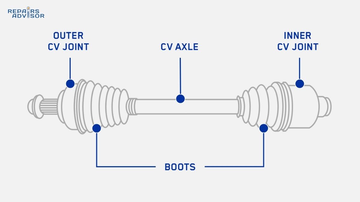
Front-wheel drive (FWD) vehicles represent the most common CV joint application. Every FWD vehicle has two complete CV axle assemblies (sometimes called half-shafts), one connecting the transmission to each front wheel. Each axle assembly incorporates two CV joints: the inner joint connects the axle to the transmission’s differential output, while the outer joint connects the axle to the wheel hub. This two-joint configuration serves distinct purposes. The outer joint must handle extreme steering angles—up to 47 degrees on some vehicles during full-lock turns—while maintaining smooth power delivery. The inner joint typically operates at smaller angles but must provide “plunge” capability, allowing the axle to effectively lengthen and shorten by 1.5 to 2.5 inches as the suspension travels up and down over bumps and dips.
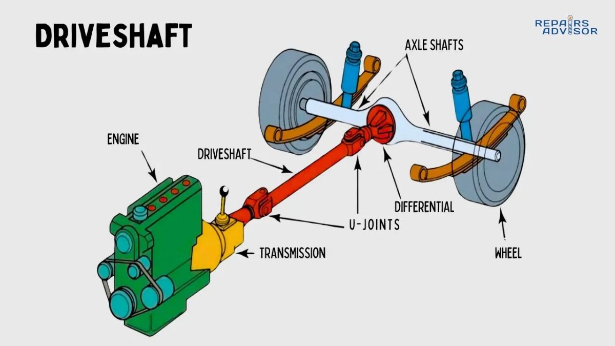
How Differential Systems Work: Torque Distribution explains how the inner CV joints receive power from the differential, while How Drive Shafts Work: Power Transmission covers the broader context of how power flows through the drivetrain.
Rear-wheel drive (RWD) vehicles with independent rear suspension also commonly incorporate CV joints, though in a different configuration. Traditional solid-axle RWD vehicles use a driveshaft with U-joints to transmit power to the rear differential, and the differential’s solid axle tubes connect directly to the wheels. However, modern RWD vehicles increasingly feature independent rear suspension for improved handling and ride quality. These systems require CV joints at each rear wheel to allow independent suspension movement while delivering power.
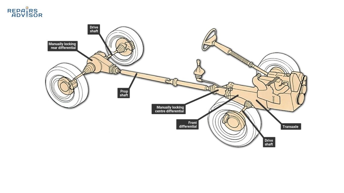
All-wheel drive (AWD) and four-wheel drive (4WD) vehicles utilize CV joints at all four wheels when equipped with independent suspension at both ends. The front axles function identically to FWD configurations, with inner plunging joints and outer fixed joints. The rear axles similarly incorporate CV joints to accommodate independent rear suspension movement. This comprehensive use of CV joints allows modern AWD vehicles to deliver power to all four wheels while maintaining excellent ride quality and handling characteristics.
How AWD Systems Work: All-Wheel Drive Coupling and How Transfer Cases Work: 4WD Operation provide deeper insight into how CV joints integrate with advanced drivetrain systems.
The historical development of CV joints traces back to 1926 when French engineers Jean Albert Grégoire and Pierre Fenaille developed the Tracta joint, the first practical constant velocity joint for automotive use. Alfred Rzeppa refined the design in 1927, creating the ball-type CV joint that bears his name and remains the dominant design for outer CV joints today.
Types of CV Joints: Rzeppa vs. Tripod Design
While both Rzeppa and tripod CV joints achieve constant velocity through geometric principles, they accomplish this goal through distinctly different mechanical designs, each optimized for specific applications and operating conditions.
Rzeppa (Ball-Type) CV Joints
The Rzeppa joint uses six precision steel balls to transfer torque while maintaining constant velocity. Six hardened steel balls (typically 15-20mm in diameter) ride in precisely machined curved grooves. The inner race, which is forged as part of or splined onto the axle shaft, contains six curved grooves on its outer surface. The outer race—a cup-shaped housing that connects to either the wheel hub or transmission—has six matching curved grooves on its inner surface. Between these races sits a steel cage that holds all six balls in precise position, ensuring they remain on the geometric plane that bisects the angle between input and output shafts.
The precision required for Rzeppa joints borders on the extreme. Each component must be machined to tolerances of 0.0001 to 0.0005 inches—that’s roughly one-tenth the thickness of a human hair. The ball grooves are ground to a mirror-smooth finish because any imperfection would cause localized stress concentrations that could lead to premature failure.
The grooves in the inner race curve in one direction, while the grooves in the outer race curve in the opposite direction. As the joint articulates, the cage automatically positions the six balls so they remain on the plane that precisely bisects the angle between the input and output shafts. This bisecting plane is the key to constant velocity: because the balls maintain contact with both races while staying on this plane, they create geometric force vectors that ensure the output shaft rotates at exactly the same speed as the input shaft, regardless of articulation angle.
Each of the six balls carries approximately 16.7% of the total transmitted torque. The contact stress between ball and groove reaches 200,000 to 300,000 psi, which is why material hardness and surface finish are so critical. Rzeppa joints excel in applications requiring maximum articulation capability. Modern designs can operate at angles up to 47-48 degrees, which is essential for the outer CV joints on front-wheel drive vehicles.
Tripod CV Joints
Tripod joints take a fundamentally different approach. Instead of six balls in curved grooves, tripod joints use a three-pointed spider (called a trunnion) with three roller bearings that ride in three parallel tracks. The spider is splined onto the axle shaft, with three arms extending outward at 120-degree intervals. Each arm carries a roller assembly consisting of a large cylindrical roller surrounding a set of needle bearings.
As the suspension moves and the axle length must change, the three rollers slide along their tracks, providing plunge capability of 1.5 to 2.5 inches—far more than any Rzeppa joint can offer. During articulation, the rollers tilt and roll within their tracks while the spider geometry automatically maintains the angle-bisecting principle that ensures constant velocity. Because the contact is rolling rather than sliding, tripod joints generate less friction and heat during operation.
This design offers several advantages that make tripod joints the preferred choice for inner CV joint positions. The superior plunge capability perfectly suits the inner joint’s primary requirement: accommodating the effective length changes as suspension moves up and down. Tripod joints also demonstrate higher torque capacity than equivalently-sized Rzeppa joints because the rolling contact distributes loads more effectively than sliding contact.
The primary limitation of tripod joints is reduced maximum articulation angle compared to Rzeppa designs. Most tripod joints are limited to angles around 20-25 degrees, which is adequate for inner joint applications where articulation comes primarily from suspension travel rather than steering input.
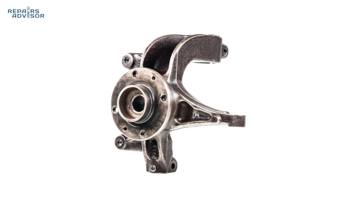
How Wheel Bearing Systems Work: Load Support & Rotation explains how CV joints work in concert with wheel bearings, while How Steering Knuckles Work: Wheel Support describes how outer CV joints connect to the steering and suspension system.
How CV Joints Work: Step-by-Step Mechanical Operation
Understanding how CV joints function through an actual driving cycle reveals the remarkable engineering that occurs every time you drive.
Step 1: Power Transfer from Transmission
Your engine’s torque flows through the transmission’s gear sets to the differential. The differential’s output shafts connect directly to the inner CV joints through splined connections—typically featuring 25 to 30 splines. The inner CV joint must immediately accommodate a challenging requirement: the transmission is relatively fixed to the chassis, but the wheel moves substantially with suspension travel. The difference between full compression and full droop can be 6 to 10 inches of total suspension travel, though the inner CV joint only needs to accommodate about 1.5 to 2.5 inches of plunge.
This is where tripod joint design proves essential. As power flows into the three-pointed spider, the three roller assemblies are positioned somewhere along their tracks in the housing—their exact position determined by the current suspension position. Each of the three rollers carries approximately one-third of the transmitted torque, with the rolling-element bearings inside each roller distributing these loads to minimize friction.
Step 2: Constant Velocity Maintenance During Articulation
As your vehicle navigates a turn, the steering input angles the outer CV joint. In a Rzeppa joint operating at a steep steering angle, the inner race and outer race are tilted relative to each other. The steel cage automatically positions the balls so they remain on the plane that bisects the angle. Each ball maintains two contact points: one where it presses against the inner race groove, and one where it presses against the outer race groove. These contact points create force vectors that ensure torque is transferred at constant velocity with zero speed fluctuation.
The specialized CV joint grease serves multiple functions at these contact points: it provides a thin lubricating film that reduces friction and wear, carries heat away from the contact zones, and cushions the micro-impacts as balls roll through their grooves. Without proper lubrication, metal-to-metal contact would quickly score the precision-ground surfaces.
Tripod joints maintain constant velocity through simpler geometry. As the inner joint articulates, the three rollers adjust their positions within their tracks. The three-point contact pattern naturally creates a balanced force distribution, and the track geometry ensures the contact points fall on the angle-bisecting plane.
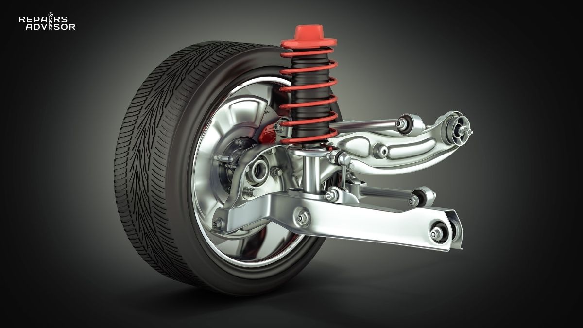
How Suspension Springs Work: Load Support describes how suspension components create the movements that CV joints must accommodate, while How Ball Joints Work: Pivot Points explains another critical articulating joint in your vehicle’s suspension system.
Step 3: Handling Suspension Movement
When your wheel hits a bump, the suspension must compress rapidly. The wheel moves upward relative to the chassis, decreasing the distance between the wheel hub and the transmission. The outer CV joint must articulate to a steeper angle, but it cannot change length—it’s a fixed joint. All of the axle length change must come from the inner CV joint, which must compress (plunge inward).
The tripod joint handles this effortlessly: the three rollers slide inward along their tracks. The rolling-element bearings inside each roller allow this motion with minimal friction, typically creating only 2-5 lb-ft of parasitic drag even during rapid plunge movements. When that wheel subsequently drops into a pothole, the exact opposite occurs, and the inner tripod joint must extend (plunge outward).
Step 4: Torque Transfer and Load Distribution
Each ball in a Rzeppa outer joint carries approximately one-sixth of the total load. At highway speeds with typical torque loads, each ball is transmitting substantial force. The contact patch where each ball touches the inner race groove is only about 2-3mm long, creating contact pressures that easily exceed 200,000 psi—roughly twice the yield strength of typical structural steel.
The engineering marvel is that these six tiny contact patches reliably transmit this torque through millions of rotation cycles. At highway speeds, each ball makes 1000 complete revolutions per minute through its groove. Over a 100,000-mile vehicle lifetime, each ball completes over 100 million revolutions, all while operating at these extreme contact pressures.
Step 5: Grease Containment and Boot Protection
Every CV joint contains approximately 3-4 ounces of specialized grease. CV joint grease differs significantly from typical automotive greases—it must withstand extreme pressure, remain stable across dramatic temperature ranges (from well below freezing to temperatures exceeding 250°F), and provide corrosion protection.
The CV boot serves as the essential containment system for this critical lubricant. Modern CV boots are manufactured from thermoplastic elastomer, synthetic rubber, or silicone rubber. The accordion-style bellows design allows the boot to expand and contract as the joint articulates and plunges, flexing through hundreds of thousands of cycles. Each end is secured with stainless steel clamps that create grease-tight seals.
When a boot tears, the CV joint’s fate is sealed. Grease immediately begins escaping, flung outward by centrifugal force. Meanwhile, water, road grit, and corrosive salt enter through the same tear. This contamination acts like lapping compound, rapidly wearing away the precision surfaces. The clicking noise you hear from a failing CV joint is literally the sound of hardened steel balls skipping and catching in worn, rough grooves.
Common CV Joint Problems and Warning Signs
CV joint failures rarely happen without warning. Understanding the progression of symptoms allows you to catch problems early.
The Classic Clicking Noise
The clicking or popping sound from a failing outer CV joint is so characteristic that experienced mechanics can diagnose the problem from description alone. You’ll hear a rhythmic clicking that starts soft but grows progressively louder, occurring only during turns (particularly sharp turns), more pronounced when accelerating through the turn, and coming distinctly from one front corner of the vehicle.
The clicking frequency correlates directly with wheel speed. Each complete wheel rotation produces six distinct clicks because each of the six balls encounters the worn section of the groove once per revolution. As the worn joint articulates during a turn, each ball rolls through its groove until it reaches a worn area. The ball momentarily catches in the depression, then “pops” or clicks as it breaks free and continues rolling.
You can perform a simple diagnostic test in a safe, empty parking lot. Turn your steering wheel fully to the left and drive slowly forward in a circle while gently accelerating. Listen carefully for clicking from the left front wheel area. Then repeat with the wheel turned fully right. The side that produces clicking has the failing outer CV joint.
Vibration During Acceleration
While outer CV joint failures announce themselves with clicking, inner CV joint problems typically manifest as vibration—a rhythmic shuddering felt through the steering wheel, floor, and seat during acceleration. The vibration is most noticeable during moderate to hard acceleration from a stop or at low speeds, often feels like a rhythmic shuddering at 3-5 pulses per second, and intensifies under load.
The mechanical explanation involves the loss of constant velocity that occurs when inner tripod joints develop excessive wear. When contamination enters through a damaged boot, the needle bearings inside the rollers can wear, allowing play. This wear allows the rollers to bind momentarily and then break free, causing tiny interruptions in the smooth power flow.
How to Spot a Bad CV Half-Shaft Boot Kit (and Protect Your Axle!) provides detailed guidance on identifying boot damage before joint problems develop.
CV Boot Damage and Grease Leakage
Most CV joint failures don’t begin with the joint itself—they begin with boot damage. The most obvious sign is grease splatter—typically black, dark gray, or occasionally brown, with a thick, sticky consistency. You’ll find it deposited on the inside surface of the wheel rim, on the brake caliper and rotor, across suspension components, and coating the inner fender well.
The boot itself may show visible tears or splits in the rubber, cracks from age-related deterioration, loose or missing clamps, or the entire boot displaced from its proper position. During inspection, gently spread the accordion folds apart to inspect for hidden cracks.
The critical question when boot damage is discovered: is it too late for boot replacement alone, or has the joint already sustained damage? If you can see fresh, wet grease around a visible tear with clean edges, the boot failure is probably recent. If grease is dried and caked, or if the boot is completely missing, significant time has elapsed. Most importantly, if clicking has begun, the joint is already damaged beyond economical repair.
Clunking When Shifting
A clunking sound or feeling when shifting between Drive and Reverse can indicate excessive wear in CV joints—typically inner joints. This symptom differs from clicking. Instead, clunking is an abrupt, single-event sound/feeling that occurs at the moment of power direction reversal.
The mechanical explanation involves backlash—the free play between mating components. New CV joints have extremely tight clearances. As joints wear, these clearances increase. When you shift from Drive to Reverse, the direction of torque application suddenly reverses, and the worn joint’s components must move through their excessive clearances before engaging on the opposite side.
Complete Joint Failure
If all warning signs are ignored, eventual catastrophic failure becomes inevitable. Symptoms include sudden, complete loss of power to one wheel, loud grinding or clanking noises, possible visible damage with broken axle shaft protruding, or complete inability to move the vehicle under its own power. In the worst case, the outer CV joint can separate completely, allowing the wheel hub to disconnect from the axle.
This progression explains why professional mechanics emphatically recommend replacing clicking CV joints promptly. While a clicking joint might survive thousands more miles, it might also fail catastrophically tomorrow when you’re accelerating onto a busy highway.
How Control Arms Work: Suspension Geometry explains how CV joints integrate with the broader suspension system.
CV Joint Location and Access Guide
Visual Identification and Location
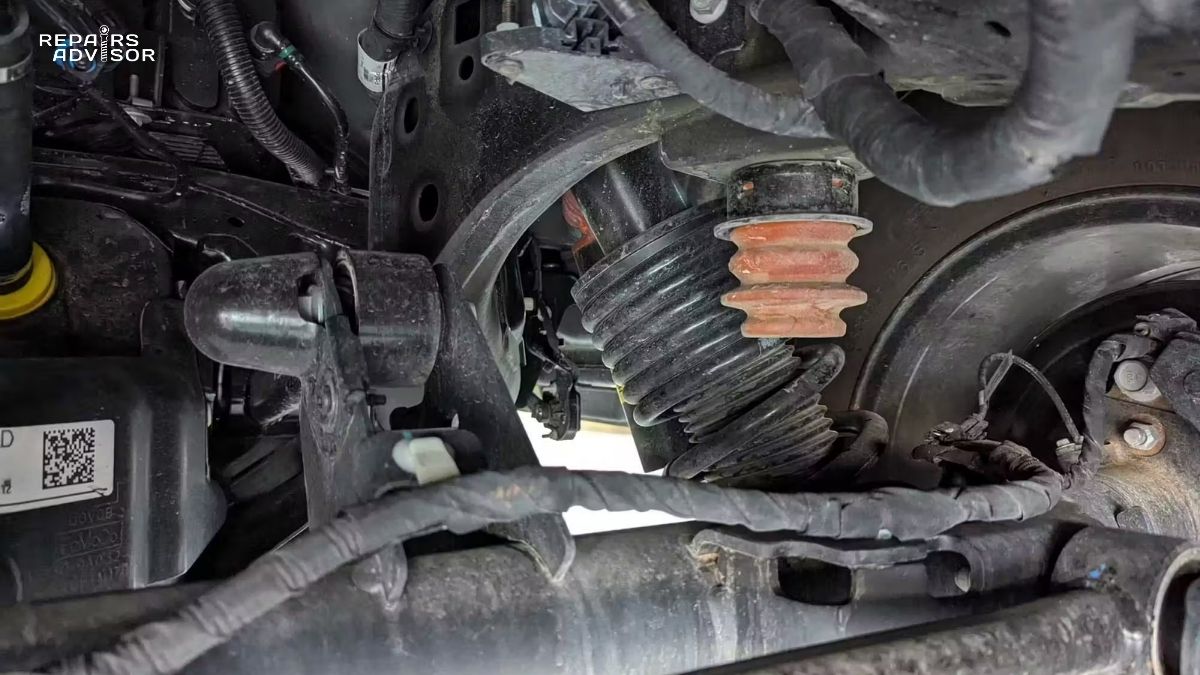
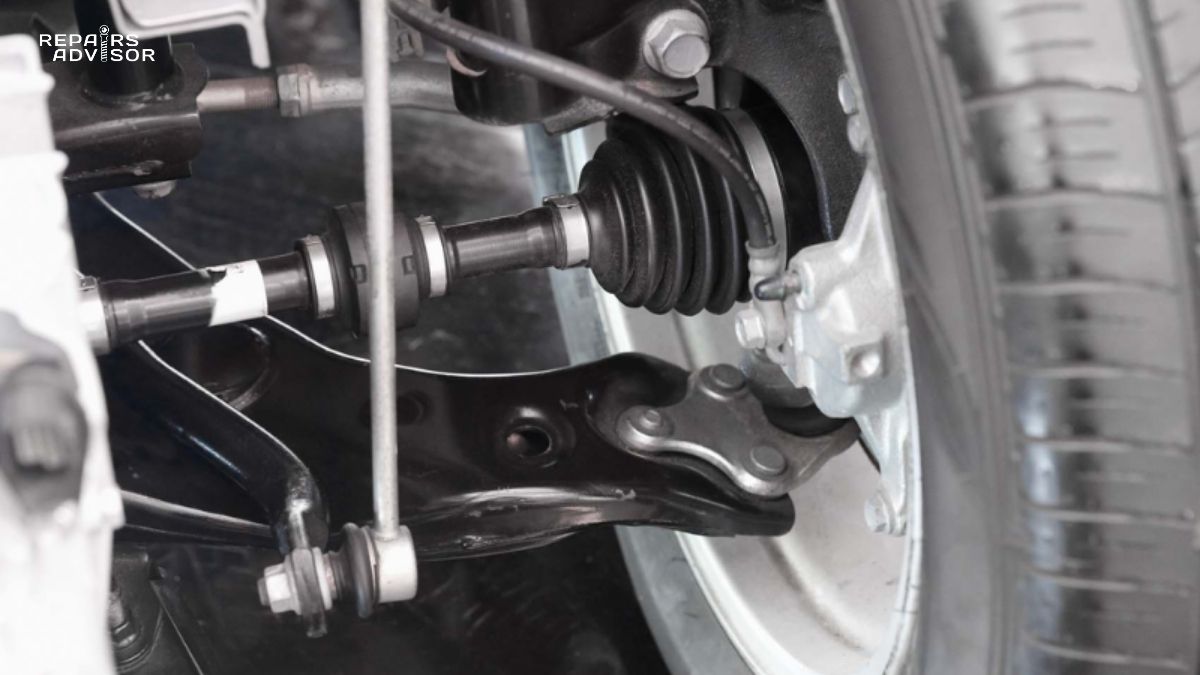
CV joints are located at both ends of each drive axle. On front-wheel drive vehicles, you’ll find them at the front wheels. The outer CV joint sits directly behind the wheel hub assembly, inside the wheel. If you look through your wheel spokes, you can often see the black rubber CV boot—the accordion-style flexible boot covering the joint, typically 3-5 inches long and 2-4 inches in diameter.
The inner CV joint resides at the opposite end of the axle, connecting to the transmission’s differential output shaft. Inner joints are typically less visible because they’re tucked behind engine and suspension components. On most FWD vehicles, the inner CV joints are partially hidden behind the engine’s oil pan and subframe.
Access for DIY Inspection
Basic CV boot inspection requires no special tools and minimal mechanical knowledge. This inspection allows you to catch boot damage early. Here’s the safe procedure:
- Park on level ground, engage parking brake
- Turn the steering wheel fully to the left while stationary
- Get down low and look through the right front wheel spokes
- Using a flashlight, inspect the visible portion of the outer CV boot
- Look for tears, cracks, loose clamps, or grease leakage
- Repeat with the wheel turned fully right to inspect the left front outer boot
For complete boot inspection, you’ll need to raise and support the vehicle safely. NEVER work under a vehicle supported only by a jack. Use proper jack stands rated for your vehicle’s weight. Position jack stands at the vehicle manufacturer’s specified support points. Ensure the vehicle is on level, stable ground. Use wheel chocks behind the wheels remaining on the ground.
With the vehicle safely supported and wheels removed, inspect all CV boots. Look for tears, cracks, splits, or damage to the rubber material. Check that both clamps on each boot are tight and properly positioned. Look for grease splatter on brake components, suspension parts, and wheel wells. Gently squeeze the boot—it should feel somewhat firm rather than collapsed and empty.
How MacPherson Strut Suspension Works: Compact Design explains the suspension components you’ll encounter when inspecting CV joints.
When Professional Inspection Becomes Necessary
While visual boot inspection is safely within DIY capability, certain situations require professional mechanical expertise: determining whether clicking originates from CV joint versus other components, testing for internal CV joint play, differentiating between CV joint vibration and other driveline vibrations, and assessing whether damaged boot has already allowed joint contamination.
Brand-specific repair procedures can be found in factory service manuals: Ford Repair Manuals, Toyota Repair Manuals, Honda Repair Manuals, or Chevrolet Repair Manuals.
CV Joint Replacement Costs and Repair Considerations
Boot Replacement vs. Complete Axle Replacement
Boot replacement might seem logical: if the boot fails but the CV joint remains undamaged, why not replace the $15-30 boot rather than the entire $60-200 axle? The primary issue is labor cost. Replacing a CV boot requires removing the axle from the vehicle (same labor as complete axle replacement), disassembling the CV joint, thoroughly cleaning all components, inspecting for contamination, repacking with fresh grease, installing the new boot, and reinstalling the axle. This process takes 1.5-3 hours—essentially the same time as complete axle replacement.
Boot replacement cost:
- Boot kit with clamps and grease: $15-30
- Professional labor: $150-360
- Total: $165-390 per axle
Compare this to complete axle assembly replacement and you’ll understand why many mechanics recommend full axle replacement: similar labor cost, guaranteed good joints, and no risk that hidden contamination will cause premature failure.
Complete CV Axle Assembly Replacement
Replacement cost estimates:
Economy/Compact Cars:
- Aftermarket remanufactured axle: $60-120
- Labor: $150-300
- Total per axle: $210-420
- Both front axles: $420-840
Midsize/Full-Size Sedans:
- Aftermarket axle: $80-150
- Labor: $200-360
- Total per axle: $280-510
- Both front axles: $560-1,020
SUVs/Trucks with AWD:
- Front or rear axle: $100-200
- Labor: $200-360
- Total per axle: $300-540
- All four axles: $1,200-2,160
Luxury/Performance Vehicles:
- OE or premium axle: $300-800+
- Labor: $240-600
- Total per axle: $540-1,400
Why complete axle replacement makes sense:
- Both inner and outer joints have similar use
- New boots included
- Warranty coverage
- Eliminates diagnostic uncertainty
DIY Replacement Feasibility
Many intermediate-skilled DIY mechanics successfully replace CV axles, saving $150-300 in labor. However, this repair requires specific tools and knowledge.
Required tools:
- Floor jack and jack stands
- Torque wrench capable of 150-200 lb-ft
- Large socket for axle nut (30-36mm)
- Ball joint separator
- Pry bar or axle puller
- Basic hand tools
- Penetrating oil
Common DIY challenges:
- Seized axle nut
- Pressed-in axle shaft
- Stuck ball joints/tie rod ends
- Transmission seal concerns
- Spline alignment during installation
When to opt for professional service:
- Limited mechanical experience
- Severe rust/corrosion concerns
- Lack of safe vehicle support equipment
- Uncertainty about any aspect of the procedure
- Newer vehicle under warranty
Post-replacement requirements:
- Wheel alignment check
- Axle nut torque verification (150-200 lb-ft)
- Test drive
- Fluid level check
How Double Wishbone Suspension Works: Superior Control explains the suspension architecture you’ll encounter during CV axle replacement.
Maintenance and Prevention Strategies
Regular Visual Inspection Schedule
The single most effective preventive measure is regular CV boot inspection.
Inspection frequency:
- Every oil change: Quick visual check through wheel spokes
- Every brake service: Thorough boot inspection with wheels removed
- After driving through deep water or mud
- Pre-winter inspection
- After any undercarriage impact
Inspection checklist:
- Tears, cracks, or holes in boot material
- Loose, damaged, or missing clamps
- Grease leakage or splatter on nearby components
- Physical damage from road debris
- Age-related deterioration
- Boot displaced from proper position
If ANY damage is found, schedule repair within 1-2 weeks. Fresh boot damage offers the best chance for successful boot-only replacement.
Driving Habits That Extend CV Joint Life
Avoid full-lock maneuvering while stationary: Turning to full lock while stationary creates maximum CV joint stress. Begin turns with less than full lock, or straighten the wheel slightly while accelerating.
Gentle acceleration through turns: The most damaging combination is maximum steering angle with hard acceleration. Moderate acceleration through turns, especially tight turns.
Minimize rough-road performance driving: Aggressive driving on rough roads creates harsh suspension articulation, high torque loads, and angular articulation simultaneously.
Be cautious of obstacles that could damage boots: Road debris impact is the most common boot damage cause. Defensive driving helps protect CV boots.
Expected Service Life
CV joint lifespan under normal conditions:
- Undamaged boots: 70,000-130,000+ miles
- OE or premium joints: Often last 200,000+ miles
- Mid-grade aftermarket: 80,000-120,000 miles
- Budget aftermarket: 50,000-80,000 miles
Factors affecting longevity:
- Driving conditions (highway vs. city, smooth vs. rough roads)
- Climate factors (extreme temperatures, ozone, salt exposure)
- Vehicle type (FWD vs. AWD, performance vs. economy)
- Maintenance (regular inspection, prompt boot replacement)
Boot damage drastically shortens life:
- Dry climate: 1,000-2,000 miles possible
- Wet conditions: 200-500 miles
- Off-road/muddy: Failure within days
How Anti-Roll Bars Work: Body Roll Control explains another suspension component that works alongside CV joints.
Conclusion and Key Takeaways
CV joints represent a masterpiece of mechanical engineering—precision components that deliver smooth, vibration-free power to wheels that must simultaneously steer, bounce, and roll. The constant velocity principle they employ enables modern vehicle configurations we take for granted.
Your Action Plan
Immediate actions:
- Inspect your CV boots now through wheel spokes
- Listen for warning signs during parking lot maneuvers
- Schedule professional inspection if you hear clicking or see grease
Ongoing maintenance:
- Add CV boot visual check to every oil change
- Request CV boot inspection during brake service
- Inspect after deep water, mud, or undercarriage impacts
- Budget for potential replacement around 100,000-150,000 miles
The Repair Decision Framework
Fresh boot tear, no clicking: Boot replacement may be viable for DIY; consider axle replacement for professional service
Clicking noise present: Complete CV axle replacement required immediately
Old boot damage, dried grease: Complete axle replacement required even without clicking yet
Vibration during acceleration: Professional diagnosis required to isolate cause
Understanding Your Skill Level
Intermediate DIY Enthusiasts (60%): You can handle CV boot inspection and identify problems. Axle replacement is within your capabilities with proper tools and safe vehicle support. Expect 3-4 hours for first attempt.
Professional Mechanics (25%): CV joint diagnosis is routine. Educate customers on why complete axle replacement makes more sense than boot-only repair. Consider OE parts for luxury vehicles and integrated ABS systems.
Beginners (15%): Learn to recognize warning signs. Understand that symptoms won’t go away on their own. Don’t ignore clicking noises or boot damage—CV joint failure can leave you stranded or create dangerous situations.
When you hear that clicking from your CV joint, you’re hearing the sound of precision destroyed by contamination. That sound is your warning to act before minor wear progresses to catastrophic failure. Heed that warning, and your CV joints will likely serve your vehicle’s entire lifespan.
Safety Disclaimer
CV joint inspection, diagnosis, and replacement involve working under or around a raised vehicle, which presents serious crushing hazards. Never work under any vehicle supported only by a jack. Use proper jack stands rated for your vehicle’s weight, positioned at manufacturer-specified support points on level, stable ground. Engage the parking brake and use wheel chocks.
CV joint failure can result in sudden loss of vehicle control, potentially causing serious accidents. If you suspect CV joint failure, have your vehicle inspected by a qualified technician promptly. Do not continue driving if symptoms are severe or if you observe broken axle components.
Improper CV axle installation can result in axle separation during driving, wheel detachment, or transmission damage. Critical fasteners including the axle nut must be torqued to exact manufacturer specifications (typically 150-200 lb-ft, vehicle-specific). After any CV axle service, wheel alignment must be checked and adjusted.
This article provides educational information about CV joint operation, symptoms, and repair options. It does not replace professional mechanical diagnosis and service. If you are uncertain about any aspect of CV joint inspection or repair, consult a qualified automotive technician. Your safety and the safety of others depends on proper diagnosis and repair of these critical drivetrain components.
Repairs Advisor provides digital repair manuals and technical information only. We do not perform repairs, provide direct repair services, or guarantee repair outcomes. The information in this article is for educational purposes and does not constitute professional mechanical advice specific to your vehicle’s condition.