Why Catalytic Converter Is Critical for Fuel Efficiency
The catalytic converter stands as one of modern vehicle engineering’s most significant emission control innovations. This exhaust treatment device transforms harmful pollutants into less toxic compounds before they exit your vehicle’s tailpipe, directly impacting both environmental compliance and fuel system efficiency. Since their widespread adoption in the 1970s, catalytic converters have reduced automotive emissions by over 90% while maintaining optimal engine performance.
For intermediate DIY enthusiasts, understanding catalytic converter operation helps diagnose common issues like check engine lights, reduced fuel economy, and failed emissions tests. Professional mechanics rely on catalyst diagnosis to identify failures ranging from catalyst substrate damage to oxygen sensor malfunctions. Even beginners benefit from recognizing when exhaust treatment problems require immediate attention versus routine maintenance.
The catalyst works in direct relationship with your vehicle’s exhaust system and oxygen sensors, forming an integrated emission control network. When functioning properly, the catalytic converter ensures your vehicle meets emission standards while maintaining the fuel efficiency your engine was designed to deliver. Problems with exhaust treatment directly affect how your exhaust manifold and downstream components perform.
Safety Note: Catalytic converters operate at extremely high temperatures (up to 1,400°F). Never work on or near the exhaust system until it has cooled completely. Emission control work often requires specialized diagnostic equipment and should be performed by qualified technicians when dealing with catalyst replacement or system modifications.
Catalytic Converter Parts and Construction Explained
Core Components
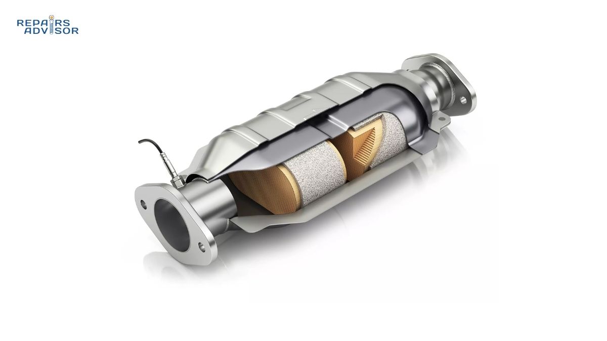
The catalyst substrate forms the heart of the exhaust treatment system. Modern catalytic converters use a ceramic honeycomb structure with thousands of tiny channels, providing maximum surface area for emission control reactions. This substrate supports the precious metal coating that performs the actual catalytic conversion. The honeycomb design allows exhaust gases to flow through while maintaining sufficient contact time with catalyst materials.
Precious metals coat the substrate channels with microscopic layers of platinum, palladium, and rhodium. These catalyst materials facilitate chemical reactions at high temperatures without being consumed in the process. Platinum and palladium handle hydrocarbon and carbon monoxide oxidation, while rhodium specializes in nitrogen oxide reduction. The specific precious metal combination varies by vehicle type and emission standards, with modern catalysts optimizing the mixture for maximum efficiency and longevity.
The converter housing protects internal components while managing extreme thermal conditions. Constructed from stainless steel, the housing withstands continuous exposure to corrosive exhaust gases and temperatures exceeding 1,200°F. The housing includes inlet and outlet connections that integrate with the exhaust manifold and downstream piping. Modern designs incorporate expansion joints to handle thermal cycling without developing leaks.
Monitoring and Protection Systems
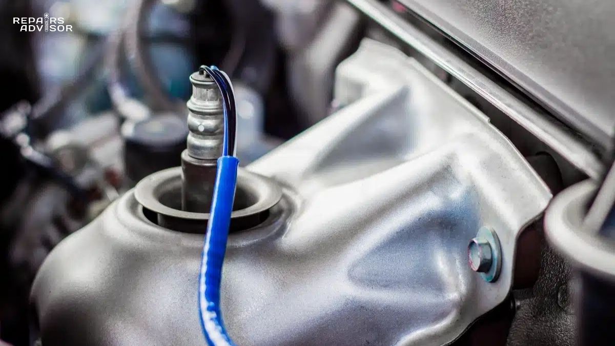
Oxygen sensors mount before and after the catalytic converter, monitoring exhaust treatment efficiency in real-time. The upstream oxygen sensor measures pre-catalyst exhaust composition, while the downstream sensor verifies catalyst performance. Your vehicle’s engine control unit compares these signals to detect catalyst degradation, triggering a check engine light when emission control efficiency falls below acceptable levels.
Heat shields surround the converter housing, protecting nearby components from extreme temperatures. Multiple layers of reflective metal create an air gap that reduces radiant heat transfer. These shields prevent thermal damage to wiring, fuel lines, and body panels positioned near the exhaust treatment system. Professional mechanics always inspect heat shield integrity during exhaust system service, as missing or damaged shields can create serious fire hazards.
The mounting system secures the catalytic converter while accommodating thermal expansion and vehicle vibration. Flanged connections use high-temperature gaskets and spring-loaded fasteners that maintain seal integrity through heating and cooling cycles. Some designs incorporate flexible joints that reduce stress transfer from engine movement. For DIY enthusiasts, proper mounting technique prevents exhaust leaks that compromise both emission control and catalyst efficiency.
Professional Tip: When replacing a catalytic converter, always install new oxygen sensors and verify proper spacing between the converter and sensors. Improper sensor placement can trigger false diagnostic codes even with a perfectly functioning catalyst.
How Catalytic Converter Works: Step-by-Step Operation
Initial Warm-Up Phase
During cold starts, the catalytic converter operates at reduced efficiency until reaching its light-off temperature around 400-600°F. Modern vehicles employ several strategies to accelerate catalyst warm-up, including retarded ignition timing and increased idle speed. The upstream oxygen sensor signals the engine control unit when the exhaust system reaches optimal emission control temperature, allowing the engine to switch from rich cold-start fueling to normal operation.
Exhaust gases flow from the exhaust manifold into the converter’s inlet, carrying unburned hydrocarbons, carbon monoxide, and nitrogen oxides. The catalyst substrate’s honeycomb structure forces these gases through thousands of channels coated with precious metals. As exhaust temperature rises, the catalyst materials become chemically active, initiating the conversion process that transforms harmful pollutants into less toxic compounds.
Three-Way Catalyst Operation
The oxidation catalyst handles hydrocarbon and carbon monoxide conversion in the first stage. Platinum and palladium facilitate oxidation reactions that combine these pollutants with oxygen molecules, producing carbon dioxide and water vapor. This process releases additional heat, helping maintain optimal catalyst operating temperature. The oxidation reactions occur continuously as long as exhaust gases contain sufficient oxygen and the catalyst remains within its operating temperature range.
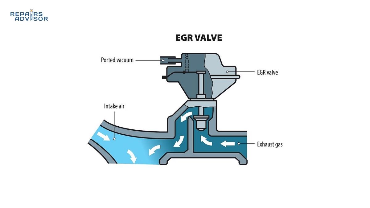
The reduction catalyst addresses nitrogen oxide emissions in the second stage. Rhodium coating facilitates reactions that split nitrogen oxide molecules, releasing nitrogen and oxygen as separate gases. This reduction process requires careful air-fuel ratio control, as too much oxygen inhibits the reaction. Your vehicle’s EGR system works alongside the catalytic converter to reduce nitrogen oxide formation in the combustion chamber, decreasing the catalyst’s workload.
Exhaust treatment efficiency depends on maintaining a precise air-fuel mixture around 14.7:1 (stoichiometric ratio). The upstream oxygen sensor continuously monitors exhaust composition, sending voltage signals to the engine control unit. The ECU adjusts fuel delivery in response, creating small oscillations around the ideal ratio. This constant adjustment ensures the catalyst receives exhaust gases in the optimal chemical composition for maximum emission control effectiveness.
Continuous Monitoring and Adaptation
The downstream oxygen sensor evaluates catalyst performance by measuring post-conversion exhaust composition. In a healthy system, this sensor shows minimal voltage fluctuation compared to the upstream sensor’s active signal. When the catalytic converter degrades, the downstream sensor signal begins mirroring the upstream pattern, indicating reduced emission control efficiency. This comparison allows the ECU to detect catalyst problems before emissions exceed legal limits.
Modern vehicles store catalyst efficiency data over time, tracking performance degradation patterns. The system considers factors like average exhaust temperature, fuel quality variations, and catalyst age when evaluating emission control system health. When catalyst efficiency drops below approximately 70% of design capacity, the ECU illuminates the check engine light and stores a diagnostic code like P0420 indicating “Catalyst System Efficiency Below Threshold.”
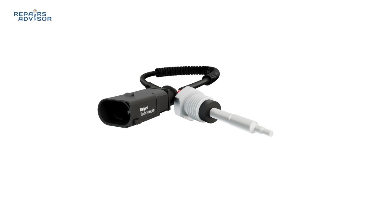
Temperature management remains critical throughout operation. Exhaust gas temperature sensors monitor catalyst operating conditions, protecting against overheating that can damage the substrate. Extreme temperatures often result from engine misfires that send raw fuel through the exhaust system, igniting inside the converter. Professional mechanics always address underlying engine problems before replacing a damaged catalytic converter to prevent repeat failures.
Warning for Beginners: Never ignore a check engine light related to the catalytic converter or oxygen sensors. Continued operation with a failing catalyst can lead to complete exhaust system blockage, resulting in engine damage and unsafe driving conditions. Have the vehicle diagnosed by a qualified technician promptly.
Catalytic Converter Location and Access Guide
Typical Mounting Positions
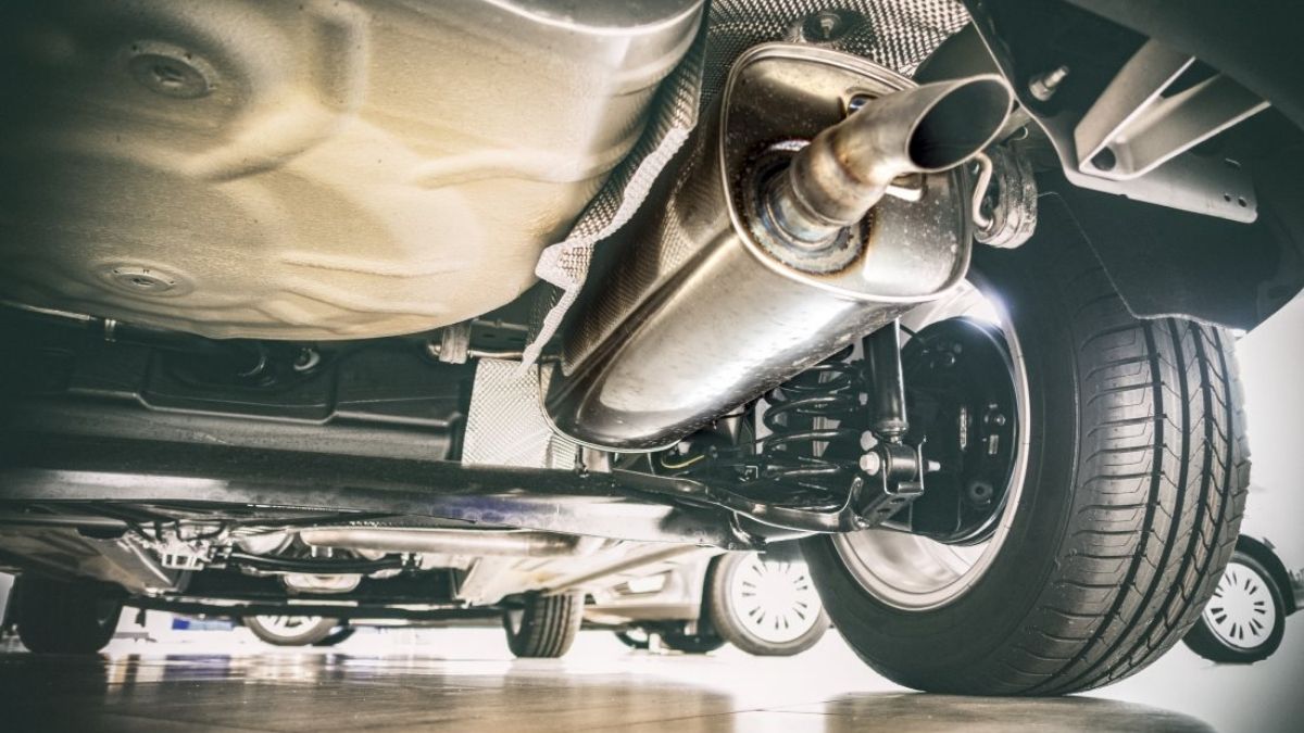
Most vehicles mount the catalytic converter between the exhaust manifold and the muffler, often directly beneath the passenger compartment floor. This location ensures rapid heat-up during cold starts while keeping the converter close enough to the engine for optimal exhaust temperature. Some vehicles use multiple catalytic converters—a small “pre-cat” near the manifold for quick light-off, and a larger main catalyst downstream for maximum emission control capacity.
V-configuration engines typically employ separate catalytic converters for each cylinder bank, mounted close to their respective exhaust manifolds. These “close-coupled” converters reach operating temperature quickly but experience more extreme thermal cycling. Understanding your vehicle’s specific exhaust treatment configuration helps when diagnosing problems or planning catalyst replacement. Consult your vehicle’s repair manual through Repairs Advisor to identify exact catalyst locations and access procedures.
Hybrid and electric vehicles with gasoline engines position catalytic converters further from the engine since these vehicles operate intermittently. The increased distance creates warm-up challenges, often addressed through active heating systems or insulated exhaust components. Professional mechanics working on hybrid battery systems must understand how the engine operating strategy affects catalyst efficiency and emission control system diagnostics.
Access Considerations and Safety
For Intermediate DIY Enthusiasts: Accessing the catalytic converter requires raising the vehicle on secure jack stands or a professional lift. Never work under a vehicle supported only by a floor jack. The exhaust system must be completely cool before beginning any inspection or service work—wait at least two hours after the engine last ran. Heat shields often obstruct direct access to mounting hardware and oxygen sensor connections, requiring removal of multiple protective panels.
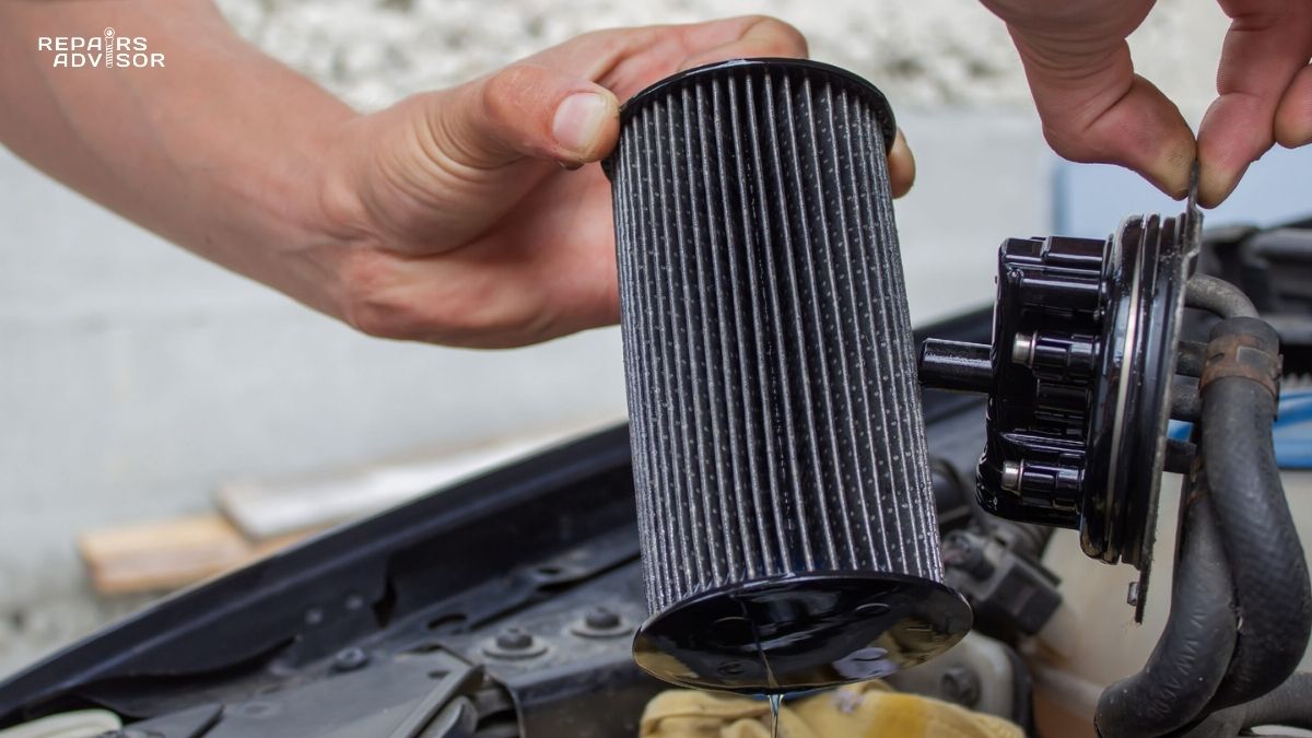
Catalytic converter inspection involves checking for physical damage, verifying heat shield integrity, and testing oxygen sensor operation. Use a mass air flow sensor cleaner to test for excessive restriction by measuring exhaust backpressure with appropriate gauges. Examine mounting gaskets for exhaust leaks that reduce catalyst efficiency by allowing unmeasured air into the exhaust stream. Document sensor readings before and after the catalyst to evaluate emission control performance accurately.
Professional Access Procedures: Mechanics use specialized diagnostic equipment to evaluate catalyst efficiency without removal. A scan tool monitors oxygen sensor switching patterns, catalyst temperature, and stored diagnostic codes. An exhaust gas analyzer measures actual tailpipe emissions, confirming whether the catalytic converter meets emission standards. When replacement becomes necessary, professionals verify the new catalyst matches the vehicle’s specific emission certification and install it with new gaskets, hardware, and oxygen sensors.
Exhaust work requires high-temperature penetrating oil applied to corroded fasteners at least 24 hours before disassembly. Rusted exhaust bolts often break during removal, potentially requiring welding or cutting tools to separate components. The diesel particulate filter in diesel vehicles requires similar access procedures but involves different diagnostic approaches. Professional mechanics always inspect the entire exhaust system during catalyst service, as problems rarely occur in isolation.
Environmental and Legal Considerations
Critical Regulatory Information: Federal and state laws strictly regulate catalytic converter replacement and modification. Using non-OEM catalysts may violate emissions regulations and void vehicle warranties. Removing or defeating emission control systems constitutes a federal offense with substantial penalties. Always install emission-certified replacement parts that match your vehicle’s year, make, and model specifications.
When replacing a failed catalytic converter, professional diagnosis determines the root cause to prevent repeat failures. Common catalyst killers include oil consumption, coolant leaks, and persistent engine misfires. Address these underlying problems before installing a new catalyst. The new converter requires an extended break-in period at moderate driving loads to properly cure the catalyst coating and achieve maximum emission control efficiency.
Recycling old catalytic converters recovers valuable precious metals while preventing environmental contamination. Scrap catalysts contain significant amounts of platinum, palladium, and rhodium that can be refined and reused. Professional recyclers pay based on catalyst size and precious metal content. Never dispose of catalytic converters with regular scrap metal—specialized recycling ensures proper handling of these high-value emission control components.
Related Content for Further Learning
Direct Emission System Components
- How Oxygen Sensors Work: Exhaust Analysis – Primary feedback sensors that monitor catalyst performance
- How EGR Systems Work: Emission Control – Complementary nitrogen oxide reduction system
- How Diesel Particulate Filters Work – Diesel emission control equivalent to catalytic converters
Exhaust System Integration
- How Exhaust Systems Work: Gas Flow & Sound Control – Complete exhaust system overview
- How Exhaust Manifolds Work: Gas Collection – Pre-catalyst exhaust component
- How Mufflers and Resonators Work: Sound Control – Post-catalyst exhaust components
Diagnostic and Troubleshooting Resources
- Signs of a Bad Catalytic Converter – Common failure symptoms and diagnosis
- Code P0420: Catalyst System Efficiency Below Threshold – Understanding the most common catalyst trouble code
- How Exhaust Gas Temperature Sensors Work – Catalyst protection monitoring systems
Information Disclaimer: This technical content is provided for educational and reference purposes only. Repairs Advisor supplies repair manuals and information but does not provide direct repair services, warranties on repair outcomes, or guarantees regarding specific procedures. Emission control system work may be subject to federal and state regulations. Always consult manufacturer specifications and qualified professionals when servicing emission control systems. For detailed service procedures and specifications, access professional repair manuals through Repairs Advisor’s extensive manual library.