The camshaft position sensor serves as your engine’s critical “sense of timing,” providing the Engine Control Module (ECM) with precise data about camshaft position and rotational speed. This small but vital electronic component ensures your engine delivers optimal performance, fuel efficiency, and emissions control through precise timing of fuel injection and ignition events.
When a camshaft position sensor begins to fail, it disrupts the delicate timing that modern engines require for proper operation. Symptoms can range from subtle performance issues to complete engine failure, making early recognition and proper diagnosis essential for preventing costly repairs and maintaining reliable transportation.
Understanding how this sensor works, recognizing failure symptoms, and knowing when professional service is necessary can save you from unexpected breakdowns and expensive engine damage. This comprehensive guide covers everything you need to know about camshaft position sensors, from basic function to advanced diagnostic procedures.
Safety Disclaimer: Camshaft position sensor diagnosis and replacement involves electrical systems and engine components. While many repairs are within DIY capability, proper diagnostic procedures and electrical safety precautions are essential. When in doubt, consult qualified automotive technicians for accurate diagnosis and professional service.
Understanding the Camshaft Position Sensor System
What Is a Camshaft Position Sensor and How Does It Work?
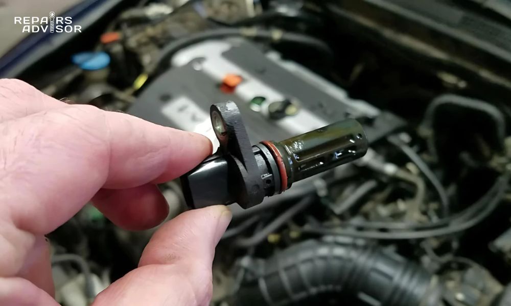
A camshaft position sensor is an electronic device that monitors the camshaft position and speed, feeding that data to the vehicle’s Engine Control Module (ECM). The ECM needs this data to control how much fuel enters the combustion chamber and ignition timing to ignite the fuel at precisely the right moment for optimal engine performance.
The sensor’s primary function revolves around timing precision. When the air/fuel mixture is ignited at precisely the right time, engine power and fuel economy increase, while tailpipe emissions decrease. This timing control requires the ECM to know exactly where the camshaft is positioned in its rotation cycle, information that only the camshaft position sensor can provide.
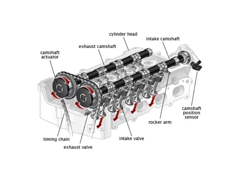
Modern engines rely heavily on this sensor data for multiple critical functions. The ECM uses camshaft position information to determine when intake and exhaust valves open and close, coordinate fuel injector timing, control ignition spark timing, and manage variable valve timing systems when equipped. Without accurate camshaft position data, the engine cannot operate efficiently or may not run at all.
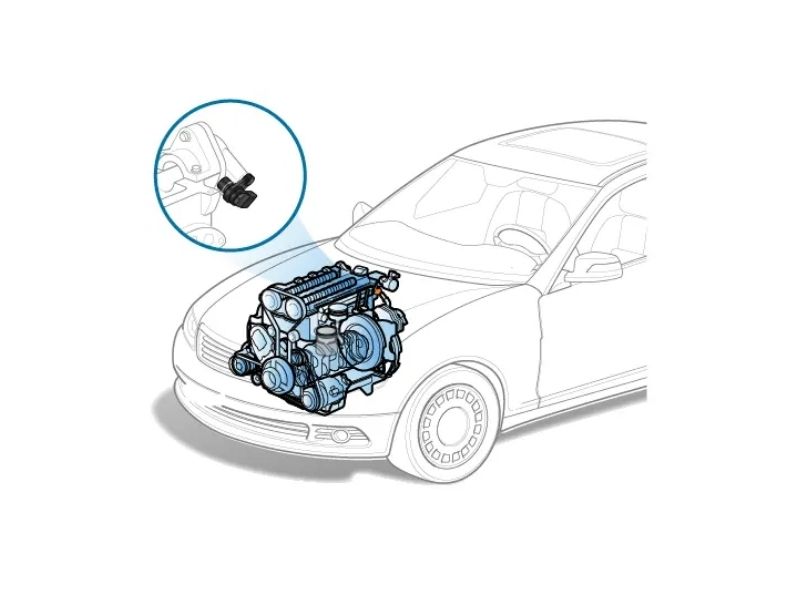
Location variations exist among different manufacturers, with sensors typically mounted near the camshaft for optimal signal detection. You may find it either in back of the cylinder head, in the lifter valley of the vehicle, or next to the engine block, depending on your vehicle’s specific design and engineering requirements.
Types of Camshaft Position Sensors
Hall Effect sensors represent the most common type of camshaft position sensor in modern vehicles. These sensors use magnetic field detection to determine camshaft position, typically employing a screen with slots and a magnet mounted on the camshaft. As the screen moves in front of or behind the sensor, it switches the sensor on and off, creating a digital signal pattern that the ECM interprets as position and speed data.
Magnetic pickup sensors generate electrical signals through magnetic field changes as metal targets or teeth on the camshaft pass by the sensor. These sensors produce analog voltage signals that vary with camshaft speed and position, providing the ECM with continuous position feedback for precise timing control.
Optical sensors, though less common, use light beam interruption for position detection. These sensors employ a light source and receiver with an interrupter disc attached to the camshaft. As the disc rotates, it alternately blocks and allows light transmission, creating position signals for the ECM.
Installation locations vary significantly among manufacturers and engine designs. Some sensors mount directly in the cylinder head near the camshaft, while others are positioned in the engine block or integrated into the timing cover. The specific location depends on camshaft accessibility, space constraints, and the need for reliable signal detection.
Integration with Engine Management Systems
ECM communication forms the heart of camshaft position sensor operation, with continuous data transmission providing real-time engine control information. The sensor sends electrical signals to the ECM multiple times per camshaft revolution, allowing the computer to track exact camshaft position and calculate rotational speed for precise timing control.
Crankshaft sensor coordination creates a comprehensive timing control system when the camshaft position sensor works together with the crankshaft position sensor. This coordination defines the exact position of the crankshaft drive and enables the ECM to precisely control fuel injection timing, ignition timing, and valve operation for optimal engine performance.
Fuel injection control depends entirely on accurate camshaft position data to determine when each cylinder’s intake valve opens and closes. The ECM uses this information to time fuel injector operation, ensuring fuel delivery occurs at exactly the right moment for complete combustion and maximum efficiency.
Ignition timing management relies on camshaft position data to control spark plug firing sequence and timing. The ECM coordinates camshaft and crankshaft position data to fire each spark plug at precisely the right moment in the combustion cycle, optimizing power output while minimizing emissions and fuel consumption.
For comprehensive understanding of related engine timing components, review our detailed guide on Camshaft: Spotting Camshaft Problems to understand the broader camshaft system and potential timing issues.
Common Camshaft Position Sensor Failure Symptoms
Primary Warning Signs
The Check Engine Light represents the most common indicator that the camshaft position sensor is failing. When your camshaft position sensor is faulty or starts having issues, the first thing you should notice is that your “Check Engine” light comes on in your dashboard. The ECM constantly monitors sensor health and upon detecting a problem, it turns on the check engine light to alert you to potential issues.
Starting problems manifest as one of the most frustrating symptoms of camshaft position sensor failure. “Hard to start” is a common symptom when your Camshaft Position Sensor has a problem. Starting takes a little bit longer than usual or doesn’t even start at all because the ECM does not get the correct values to time the spark and injected fuel required for engine ignition.
Engine stalling creates dangerous driving situations when camshaft position sensor problems worsen. A failing camshaft position sensor begins losing its ability to quickly transfer data, and unpredictable stalling can occur during driving or idling. This intermittent failure can cause your car to stall unexpectedly while driving or idling, creating potentially hazardous situations.
Rough idling becomes noticeable when the sensor provides incorrect timing data to the ECM. When you start the engine, it idles roughly if the Camshaft Position Sensor has a problem. The ECM gets incorrect camshaft data from the sensor and commands the spark plugs to spark at the wrong time, causing misfires that result in rough, unstable idle conditions.
Performance-Related Symptoms
Poor acceleration occurs when mismatched fuel delivery and ignition timing reduce engine power output. Receiving incorrect data from the Camshaft Position Sensor also reduces engine power dramatically. Acceleration is inhibited by misfires and poor combustion, with data received by the ECM from a failing sensor causing timing errors that rob the engine of power and responsiveness.
Reduced fuel efficiency results from disrupted timing that leads to incomplete combustion and increased fuel consumption. The incorrect signal from the sensor to the fuel injector causes poor fuel combustion. This inefficiency reduces gas mileage and increases operating costs as the engine works harder to produce the same power output.
Engine misfiring creates noticeable roughness and power loss when incorrect spark timing causes irregular combustion. Mismatched fuel delivery and ignition timing, even if off by a few milliseconds, will cause your vehicle to sputter, accelerate poorly, lack power, stall or even shut off due to timing disruption.
Power reduction affects overall engine performance as timing inaccuracies prevent optimal combustion efficiency. With incorrect data feeding into the engine system, you might notice sluggish acceleration or reduced power during drives, particularly noticeable during highway merging or hill climbing situations.
Advanced Failure Indicators
Transmission problems can develop when camshaft position sensor data inaccuracies affect shift solenoid operation and gear shifting. Data received by the ECM from a failing camshaft position sensor can keep transmission shift solenoids from operating and gears from shifting properly, as the transmission control module relies on accurate engine timing data for optimal shift points.
Limp mode activation may occur as the ECM triggers protective mode to prevent further engine damage when sensor data becomes unreliable. Your car may also go into limp mode to prevent further damage when the ECM detects serious timing control problems that could cause internal engine damage.
Unburned fuel smell indicates incomplete combustion from timing issues that prevent proper air/fuel mixture ignition. There is the smell of unburned fuel when combustion timing problems cause some fuel mixture to reach the exhaust pipe without being burned, creating distinctive fuel odors and increased emissions.
Engine overheating can result from severe timing problems that cause excessive heat generation during combustion. When timing becomes significantly disrupted, combustion efficiency drops while heat generation increases, potentially causing engine temperature problems that require immediate attention.
Progressive Failure Patterns
Intermittent symptoms characterize initial sensor degradation, causing occasional performance issues that worsen over time. As a camshaft position sensor weakens, so does the data it transmits to the ECM, creating inconsistent engine operation that may seem to come and go randomly.
Worsening performance follows as symptoms become more frequent and severe with continued sensor deterioration. Initially minor timing issues become more pronounced, affecting daily driving and making the problems impossible to ignore.
Complete failure eventually occurs when the data signal becomes too weak for ECM recognition. Eventually the data signal becomes so weak the ECM switches off fuel and spark delivery, and your engine will not start. This represents the final stage of sensor failure requiring immediate replacement.
Cascade effects can result from ignoring symptoms, potentially leading to expensive engine or transmission damage. Please do not ignore or postpone scanning your vehicle or getting it inspected when your Check Engine light turns on or else your engine could end up getting seriously damaged. The engine could even end up failing altogether, requiring complete rebuilds or replacement.
For comprehensive engine diagnostic procedures and troubleshooting techniques, explore our Diagnostics & Troubleshooting section for professional diagnostic methods and trouble code interpretation.
Causes of Camshaft Position Sensor Failure
Environmental and Operating Factors
Heat exposure represents the primary cause of camshaft position sensor degradation over time. Because of the heat that is produced by the engine, the camshaft position sensor, just like any other sensor or switch on a vehicle, will be subjected to a significant amount of wear and tear. Engine compartment temperatures can exceed 200°F during normal operation, causing gradual breakdown of sensor electronics and housing materials.
Water damage occurs when moisture enters the engine compartment, causing sensor corrosion and electrical problems. If water enters the engine compartment, the sensor may stop working because of corrosion or electrical problems that affect signal transmission and sensor reliability. Even minor water intrusion can cause long-term reliability issues.
Oil contamination affects sensor functionality when oil leaks coat sensor surfaces and interfere with proper operation. If there’s an oil leak, it can seep into the sensor and coat its surface. This affects its functionality and causes sensor failure by disrupting magnetic field detection or electrical connections.
Vibration stress contributes to sensor wear and connection problems through constant engine vibration transmitted to sensor mounting points. Continuous engine vibration can loosen electrical connections, crack sensor housings, or damage internal components over time.
Electrical and Mechanical Issues
Wiring problems create sensor failures through damaged sensor wires, short circuits, or connection issues that disrupt signal transmission. Electrical problems like a short circuit, damaged sensor wires, or spark plug issues, can cause sensor failure even when the sensor itself remains functional.
Corrosion affects metal sensor components when harsh driving conditions cause rust and oxidation that interfere with sensor operation. The metal parts of the sensor can rust if exposed to harsh driving conditions or issues such as water damage and oil leaks, creating electrical resistance and signal problems.
Physical damage can occur from impact or mechanical stress that damages sensor housing or internal components. Road debris, maintenance accidents, or engine component failures can physically damage sensors, requiring immediate replacement.
Age-related wear represents normal degradation of electrical components over the vehicle’s lifetime. The camshaft position sensor in a vehicle is constructed to have the same lifespan as the car itself. Still, in the vast majority of situations, it will need to be replaced far earlier than that due to cumulative stress and component aging.
Related System Problems
Timing component wear can create symptoms similar to sensor failure when stretched timing belts or worn tensioners affect camshaft timing. If you cannot identify any issues with the Camshaft Position Sensor or the circuit, you may have a timing belt or tensioner that has become brittle or overstretched due to excessive use.
Engine mechanical issues can affect sensor operation when internal engine problems create abnormal vibration, timing variations, or mounting stress that impacts sensor performance and reliability.
ECM problems may appear as sensor failures when engine control module issues prevent proper sensor signal interpretation or processing. Sometimes the problem lies with the computer rather than the sensor itself.
Electrical system faults, including alternator or battery problems, can affect sensor power supply and create symptoms that mimic sensor failure. Proper electrical system operation is essential for reliable sensor function.
For related engine timing component information, review our guide on Balance Shaft: Mitigating Engine Vibration for Smooth Operation to understand engine timing system complexity and interrelated components.
Diagnostic Procedures and Testing Methods
Professional Diagnostic Tools and Techniques
OBD-II scanning provides the primary diagnostic method for camshaft position sensor problems, using scan tools to read error codes stored in the ECM. If your light comes on you must take your car to be examined by a technician, or you can use a DIY scanner tool to check the vehicle for stored diagnostic trouble codes that indicate specific sensor problems.
Multimeter testing enables measurement of resistance, voltage, and signal integrity to verify proper sensor operation. Locate the power, signal and ground wires of the sensor. Test them with a multimeter according to the directions in your factory manual. If the readings aren’t correct, replace the sensor to restore proper operation.
Oscilloscope analysis provides advanced testing of sensor signal patterns and timing for comprehensive diagnosis of intermittent problems. Professional technicians use oscilloscopes to analyze sensor waveforms, signal frequency, and timing relationships that basic multimeters cannot detect.
Visual inspection remains essential for checking physical damage, corrosion, or contamination that might affect sensor operation. Remove the sensor and examine it for signs of damage or contamination that could interfere with proper signal generation or transmission to the ECM.
Common Diagnostic Trouble Codes
P0340 indicates Camshaft Position Sensor Circuit Malfunction, suggesting problems with sensor wiring, connections, or internal sensor failure that prevents proper signal transmission to the ECM.
P0341 represents Camshaft Position Sensor Performance Problems, indicating the sensor provides signals outside expected parameters but maintains basic circuit integrity. This code often indicates sensor degradation or timing issues.
P0342 signals Camshaft Position Sensor Low Input, meaning the sensor signal voltage is below ECM expectations. This typically indicates wiring problems, poor connections, or sensor internal failure.
P0343 indicates Camshaft Position Sensor High Input, showing sensor signal voltage exceeds normal parameters. This usually suggests short circuits, damaged wiring, or sensor internal problems.
Code interpretation requires understanding what each diagnostic trouble code indicates about sensor condition and the specific type of failure occurring. Professional diagnosis considers code patterns, freeze frame data, and symptom correlation for accurate problem identification.
Step-by-Step Diagnostic Process
Initial assessment begins with checking for obvious symptoms and warning lights that suggest camshaft position sensor problems. Note any check engine light activation, starting difficulties, rough idle, or performance issues that correlate with sensor failure patterns.
Code retrieval uses OBD-II scanners to identify stored diagnostic codes and freeze frame data. A diagnostic scan may reveal specific fault codes pointing to a failing crankshaft or camshaft position sensor, providing the starting point for focused diagnostic procedures.
Visual inspection examines the sensor, wiring, and connections for obvious damage, corrosion, or contamination. Look for oil contamination, water damage, physical damage, or corroded connections that could cause sensor problems.
Electrical testing verifies power supply, ground, and signal circuits using multimeter measurements. Test sensor power supply voltage, ground circuit continuity, and signal wire integrity according to manufacturer specifications.
Signal analysis tests sensor output under various operating conditions to verify proper signal generation and timing. This may require running the engine at different speeds while monitoring sensor output patterns.
System correlation checks related sensors and timing components to rule out mechanical problems that might create similar symptoms. Consider crankshaft position sensor operation, timing belt condition, and other timing-related components.
Differential Diagnosis Considerations
Crankshaft sensor vs. camshaft sensor problems often create similar symptoms, requiring specific diagnostic procedures to distinguish between these related but different sensors. Both sensors affect engine timing and operation, but serve different functions in the engine management system.
Timing component problems must be distinguished from sensor issues when mechanical wear creates symptoms similar to sensor failure. Stretched timing belts, worn tensioners, or jumped timing can create performance problems that mimic sensor failures.
Fuel system correlation helps rule out fuel delivery problems that might create similar performance symptoms. Poor fuel pressure, clogged injectors, or fuel quality issues can cause performance problems similar to timing sensor failures.
Ignition system checks verify spark delivery and timing components to ensure ignition problems aren’t creating symptoms attributed to camshaft position sensor failure. Faulty spark plugs, ignition coils, or ignition timing problems can cause similar symptoms.
For comprehensive engine sensor diagnostic procedures, consult our technical resources and professional diagnostic guides to understand the complex relationships between engine sensors and systems.
Camshaft Position Sensor Replacement Process
Replacement Complexity Assessment
DIY feasibility makes camshaft position sensor replacement generally straightforward for individuals with basic mechanical skills and proper tools. If you plan to change the camshaft position sensor yourself, it’s not a difficult job. You would save the labor fee and only have to pay for parts, making this repair accessible to many vehicle owners.
Tool requirements include basic hand tools, OBD-II scanner for code clearing, and multimeter for testing. Most replacements require only common tools such as socket sets, screwdrivers, and electrical connection tools, though some applications may require special access tools.
Safety considerations involve battery disconnection and proper handling procedures to prevent electrical damage or personal injury. Always disconnect the negative battery cable before beginning electrical work and follow proper electrical safety procedures throughout the replacement process.
Time investment typically ranges from 1-2 hours depending on sensor location and vehicle design. Most sensors are reasonably accessible, though some may require removal of engine covers, air intake components, or other parts for proper access.
Step-by-Step Replacement Procedure
Safety preparation begins with disconnecting the negative battery cable to protect electronics and ensuring the engine is cool to prevent burns. Never work on hot engines, and always use proper safety equipment including eye protection and work gloves.
Sensor location requires finding the sensor using service manual information or online resources specific to your vehicle. Different car manufacturers will have their own unique spot near the engine for mounting the sensor, requiring vehicle-specific location information.
Access clearance may require removing components blocking sensor access such as engine covers, air intake components, or wiring harnesses. Some sensors are easily accessible while others require significant component removal for proper access.
Electrical disconnection involves carefully disconnecting the sensor wiring harness by releasing the tab that’s holding the connector in place. Handle electrical connections carefully to prevent damage to wiring or connector terminals.
Sensor removal requires removing the mounting bolt attaching the sensor to the engine and carefully pulling the sensor free. It may require a small twisting motion to remove the sensor from its mounting location without damaging the O-ring or sensor body.
Installation preparation includes taking out your new sensor and applying a small amount of oil to the O-ring to ensure proper sealing and easy installation. Clean the sensor mounting area and inspect for damage before installation.
Installation involves putting the new sensor in its place, securing it with the mounting bolt, reconnecting the wiring, and reconnecting the negative battery terminal. Follow proper torque specifications for the mounting bolt to prevent damage.
System reset may require clearing diagnostic codes and performing any required relearning procedures. In some cases, the camshaft position sensor will work right out of the box. Other vehicles require a relearning or recalibration of the sensor that varies by manufacturer.
Professional Service Considerations
Complex installations may require extensive disassembly for sensor access on certain vehicles, making professional service more practical and cost-effective than DIY attempts. Some sensors are mounted in locations that require special tools or extensive component removal.
Calibration requirements affect certain vehicles that need professional sensor relearning procedures using specialized diagnostic equipment. These procedures ensure proper sensor operation and timing correlation with other engine systems.
Quality assurance through professional installation ensures proper torque specifications, electrical connections, and system integration. Professional technicians have experience with specific vehicle requirements and potential complications.
Warranty coverage typically accompanies professional service, providing protection against parts failure or installation problems. Professional installation often includes warranties on both parts and labor for added peace of mind.
Post-Replacement Procedures
Code clearing removes diagnostic codes from ECM memory and verifies repair success through system testing. Use an OBD-II scanner to clear codes and monitor for recurring problems that might indicate other issues.
Test drive evaluation monitors engine performance and sensor operation under various driving conditions. Pay attention to starting, idle quality, acceleration, and overall engine performance to verify successful repair.
Relearning procedures may be required for some vehicles to allow ECM adaptation to the new sensor. Check your service manual for specific relearning requirements and procedures for your vehicle application.
Long-term monitoring involves watching for recurring symptoms that might indicate other underlying issues requiring attention. Keep records of the repair for future reference and warranty purposes.
For related camshaft system components and timing issues, review our comprehensive guide on Camshaft Actuator: What’s That Little Helper on Your Camshaft? to understand variable valve timing systems and their sensor requirements.
Cost Analysis and Service Planning
Replacement Cost Breakdown
Parts cost for camshaft position sensors typically ranges from $25-75 for most applications, with OEM sensors generally costing more than aftermarket alternatives. On average, expect to spend $100 to $250 to have the camshaft position sensor replaced. The parts may cost $75 to $125, representing a significant portion of the total repair cost.
Labor charges for professional installation typically cost $75-150, depending on sensor accessibility and local labor rates. While the labor makes up $25 to $125 of the total cost, complex installations or difficult access locations can increase labor time and costs significantly.
Total replacement cost averages $100-250 depending on vehicle complexity, parts selection, and regional labor rates. The total cost depends on the make and model of your vehicle, as well as local labor rates and whether OEM or aftermarket parts are selected.
Premium vehicle costs may reach $200-400+ for luxury cars, performance vehicles, or applications requiring extensive disassembly for sensor access. European and luxury vehicles often have higher parts costs and more complex installation requirements.
Cost Variables and Considerations
Vehicle complexity affects labor time and costs, with some engines providing easy sensor access while others require extensive component removal. Engine design, sensor location, and component accessibility significantly impact total repair costs.
OEM vs. aftermarket parts present a cost vs. quality decision, with original equipment parts typically offering better reliability and longer service life despite higher initial costs. Consider long-term value when selecting replacement parts.
Regional labor rates create significant geographic variation in service costs, with urban areas typically commanding higher labor rates than rural locations. Shop around for competitive pricing while ensuring qualified service.
Diagnostic fees may add $100-150 to total costs for proper problem identification and testing. While this increases immediate costs, proper diagnosis prevents unnecessary parts replacement and ensures accurate repair.
Cost-Benefit Analysis
Preventive value makes early sensor replacement cost-effective compared to engine damage from continued operation with faulty sensors. Addressing sensor problems promptly prevents more expensive engine timing or performance issues.
Fuel efficiency improvements result from proper sensor operation that optimizes combustion timing and reduces fuel consumption. The improved fuel economy can offset repair costs over time through reduced operating expenses.
Reliability improvement eliminates stalling, starting problems, and performance issues that affect daily transportation dependability. Reliable transportation has value beyond simple repair costs.
Resale value benefits from documented repairs that maintain vehicle reliability reputation and proper maintenance records. Well-maintained vehicles with current repairs command higher resale prices.
Service Timing and Planning
Symptom-based replacement should address issues immediately when symptoms appear to prevent further problems and maintain reliable transportation.
Preventive maintenance may include sensor replacement during major engine service when access is already available, potentially reducing total labor costs.
Multiple sensor vehicles with DOHC or V-configuration engines may benefit from replacing all sensors simultaneously to prevent future service calls and labor duplication.
Warranty considerations favor professional service that provides protection against premature failure and ensures proper installation according to manufacturer specifications.
For vehicle-specific service information and technical specifications, consult our comprehensive manual collections including FORD Manuals for detailed camshaft position sensor service procedures.
Vehicle-Specific Applications and Considerations
Common Applications by Manufacturer
Domestic vehicles including Ford, GM, and Chrysler applications typically use Hall Effect sensors with standardized mounting locations and electrical connections. These sensors generally provide straightforward replacement procedures with readily available parts and service information.
Import applications such as Honda, Toyota, and Nissan vehicles often feature reliable sensor designs with good accessibility and reasonable replacement costs. Japanese manufacturers typically engineer sensors for longevity and serviceability.
European vehicles including BMW, Mercedes, and Audi may have more complex sensor systems requiring specialized diagnostic procedures and higher-cost replacement parts. These applications often integrate sensors with other engine management systems.
Performance applications and modified engines may require specialized sensors or non-standard installation procedures that affect replacement complexity and cost considerations.
Multiple Sensor Systems
DOHC engines with dual overhead camshafts often have multiple camshaft sensors, typically one per camshaft, requiring coordinated replacement and calibration procedures. Some cars can have multiple camshaft position sensors with the number varying depending on the number of camshafts in the engine.
V-configuration engines may have separate sensors for each cylinder bank, with V6 and V8 engines potentially requiring multiple sensor replacement for complete system service. Most modern engines have one sensor per camshaft, so cars might have one, two, or even four sensors.
Variable valve timing equipped engines require additional sensor considerations for VVT system operation and timing control. These systems often integrate camshaft position sensors with VVT actuators and control systems.
Diesel applications have specific sensor requirements and timing needs that differ from gasoline engines, often requiring specialized diagnostic procedures and replacement parts designed for diesel operating conditions.
Known Problem Areas and Service Updates
Manufacturer recalls address known sensor problems and updated replacement procedures that may affect specific vehicle models or production years. Stay informed about recalls and service campaigns that might cover sensor replacement costs.
Service bulletins provide factory updates addressing common sensor failures, improved replacement procedures, or updated diagnostic methods. These bulletins often contain valuable troubleshooting information and repair techniques.
Improved designs represent updated sensor designs that address known weaknesses in original equipment, often providing better reliability and longer service life than original parts.
Preventive measures include manufacturer recommendations for extended sensor life through proper maintenance, environmental protection, and early problem recognition.
Special Service Considerations
Access challenges affect certain applications where sensors are mounted in difficult locations requiring special procedures, tools, or extensive component removal for replacement access.
Calibration requirements vary among manufacturers, with some vehicles needing specific relearning procedures using professional diagnostic equipment to ensure proper sensor operation and timing correlation.
Tool requirements may include special tools for certain applications, particularly European vehicles or performance applications that require proprietary diagnostic equipment or installation tools.
Service complexity considerations help determine whether DIY replacement is practical or if professional service provides better value through specialized knowledge, tools, and warranty coverage.
For comprehensive vehicle-specific information, consult our technical resources including HONDA Manuals and TOYOTA Manuals for detailed sensor specifications and service procedures.
Prevention and Maintenance Best Practices
Preventive Maintenance Strategies
Regular inspections should include sensor evaluation during routine maintenance to identify potential problems before they cause failures. Include camshaft position sensor inspection as part of comprehensive engine system evaluation during scheduled service intervals.
Electrical system care involves maintaining proper battery and charging system operation to ensure stable sensor power supply and prevent electrical problems that could affect sensor operation or longevity.
Oil change discipline through regular oil changes prevents contamination-related failures by keeping oil leaks from affecting sensor operation. Clean engine oil reduces the likelihood of oil contamination that can coat sensor surfaces and disrupt operation.
Engine cleanliness maintenance keeps the engine compartment clean and free of debris that could damage sensors or interfere with proper operation. Regular cleaning prevents accumulation of contaminants that might affect sensor function.
Early Detection Methods
Performance monitoring involves paying attention to subtle changes in engine operation that might indicate developing sensor problems. Notice changes in starting characteristics, idle quality, or acceleration performance that could suggest sensor degradation.
Diagnostic scanning during routine maintenance can identify developing problems before they cause noticeable symptoms. Periodic code scans reveal stored diagnostic information that indicates sensor performance degradation.
Professional inspections include sensor evaluation during major services when technicians can assess sensor condition and recommend replacement based on age, mileage, or observed wear patterns.
Documentation maintenance involves keeping records of sensor replacement and related repairs to track service history and identify patterns that might indicate other underlying problems.
Environmental Protection
Moisture prevention addresses water intrusion problems promptly to prevent sensor damage from corrosion or electrical problems. Fix water leaks and ensure proper drainage to protect electrical components.
Heat management ensures proper engine cooling system operation to minimize heat-related sensor degradation. Maintain cooling system components and address overheating problems that accelerate sensor wear.
Contamination control involves fixing oil leaks and maintaining a clean engine compartment to prevent sensor contamination that could affect operation or cause premature failure.
Vibration reduction addresses engine mount problems that create excessive vibration stress on sensors and electrical connections. Proper engine mounting reduces mechanical stress on sensors.
For comprehensive engine system maintenance strategies, explore our Engine category resources for detailed maintenance procedures and expert recommendations.
Safety Considerations and Professional Recommendations
Safety Warnings and Precautions
Driving limitations become important when sensor problems affect engine operation, as continued driving with significant sensor problems risks engine damage and creates safety concerns from unpredictable stalling or performance loss.
Stalling dangers require understanding the risks of unpredictable engine stalling during driving. This is only a frustrating inconvenience if it happens while your car is parked, but it can be a dangerous situation if your car shuts off while you’re driving.
Diagnostic importance emphasizes never ignoring check engine light activation, as this warning indicates problems that require immediate attention. Ignoring the Check Engine light can lead to expensive engine or transmission repairs that far exceed sensor replacement costs.
Professional consultation becomes essential for complex diagnostic situations involving multiple codes, recurring problems, or symptoms that don’t clearly indicate sensor failure.
When to Seek Professional Help
Multiple codes indicate complex diagnostic situations requiring professional analysis when several diagnostic trouble codes appear simultaneously, suggesting system-wide problems rather than simple sensor failure.
Recurring problems after sensor replacement suggest underlying issues that require professional diagnostic expertise to identify root causes and prevent repeat failures.
Access difficulties make professional service practical when sensors are located in positions requiring special tools, extensive disassembly, or specialized knowledge for proper replacement.
Calibration needs affect vehicles requiring professional relearning procedures using specialized diagnostic equipment that may not be available to DIY mechanics.
Emergency Procedures
Stalling response requires safe procedures when the engine stalls during driving, including safely moving to the roadside, activating hazard lights, and arranging for professional assistance.
No-start situations demand appropriate response to complete sensor failure, including understanding when the problem requires immediate professional attention versus simple troubleshooting.
Temporary solutions help determine when continued driving might be safe versus when immediate professional service is necessary to prevent engine damage or safety hazards.
Professional contact information should be readily available when immediate professional assistance becomes necessary for safety or preventing further damage.
For related engine component information and diagnostic procedures, review our guide on Understanding a Bad Connecting Rod to understand engine internal component problems and their relationship to timing issues.
Conclusion
The camshaft position sensor serves as your engine’s critical “sense of timing,” providing essential data that enables the ECM to optimize fuel injection, ignition timing, and overall engine performance. Understanding this sensor’s function, recognizing failure symptoms, and knowing when to seek professional help can prevent costly engine damage and maintain reliable transportation.
Key takeaways for camshaft position sensor maintenance:
- Early symptom recognition prevents expensive engine damage through prompt attention to check engine lights, starting problems, and performance issues
- Most sensor replacements are DIY-friendly for mechanically inclined individuals with basic tools and electrical knowledge
- Professional diagnosis provides value for complex problems, multiple codes, or vehicles requiring specialized calibration procedures
- Cost-effective repair typically ranges from $100-250, representing excellent value compared to potential engine damage
Professional consultation becomes essential when diagnostic complexity exceeds DIY capabilities or when proper calibration procedures require specialized equipment. The relatively low cost and straightforward replacement procedure make camshaft position sensor service an excellent preventive maintenance investment.
Proper sensor maintenance through regular inspections, environmental protection, and prompt attention to symptoms ensures reliable engine operation and prevents the cascade of problems that can result from ignoring timing control issues. When symptoms develop, addressing them promptly protects both your engine investment and your transportation reliability.
For comprehensive technical information about camshaft position sensors and related engine components, Repairs Advisor provides detailed service manuals and expert guidance to support both professional technicians and DIY enthusiasts in maintaining optimal engine performance.
Remember: While camshaft position sensor replacement is often within DIY capability, proper diagnostic procedures and electrical safety precautions are essential. When uncertain about diagnosis or replacement procedures, professional service ensures accurate problem identification and proper repair completion.
Contact Repairs Advisor at [email protected] for technical manual assistance or visit our Help Center for additional automotive diagnostic and repair resources.