The Anti-lock Braking System (ABS) represents one of the most significant safety advances in automotive technology. This sophisticated system prevents wheel lockup during emergency braking situations, allowing drivers to maintain steering control while stopping. Understanding how your vehicle’s ABS works can help you recognize potential problems early and ensure optimal braking performance when you need it most.
Safety Disclaimer: Information provided is for reference only. Brake system maintenance and repairs should be performed by qualified technicians. Improper brake system work can result in brake failure and serious accidents. Always consult your vehicle’s service manual and seek professional assistance.
What Is an Anti-lock Braking System?
Basic Definition and Purpose
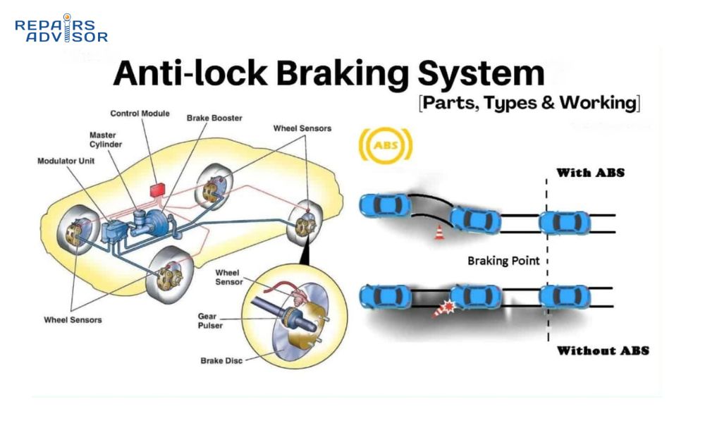
An Anti-lock Braking System (ABS) is an electronic safety system that prevents the wheels of a vehicle from locking up during braking. When wheels lock up, they stop rotating while the vehicle continues to slide forward, causing loss of steering control and potentially longer stopping distances. ABS monitors wheel speed and automatically modulates brake pressure to maintain optimal braking force without wheel lockup.
The primary purpose of ABS extends beyond simply preventing skidding. The system maintains tire traction with the road surface, preserves steering capability during emergency stops, and optimizes braking efficiency across various road conditions. This technology has become so fundamental to vehicle safety that it’s now mandatory equipment on all new vehicles in many countries.
Evolution from Standard Braking Systems
Traditional braking systems rely entirely on the driver’s ability to modulate brake pedal pressure. In emergency situations, drivers often apply excessive force, causing wheels to lock and the vehicle to skid uncontrollably. Early anti-lock systems were developed for aircraft in the 1920s, but automotive applications didn’t become practical until electronic sensors and computer control modules became affordable in the 1970s.
Modern ABS systems represent decades of refinement in sensor technology, hydraulic control, and electronic processing. Today’s systems can cycle brake pressure up to 15 times per second, far faster than any human driver could manage manually. This rapid response capability makes ABS an essential component of modern vehicle safety systems.
Regulatory Requirements and Standards
The National Highway Traffic Safety Administration (NHTSA) has required ABS on all passenger vehicles manufactured after September 1, 2013. Similar regulations exist in Europe, Canada, and Australia. These requirements recognize ABS as a proven technology for reducing accidents and fatalities.
Automotive manufacturers must meet specific performance standards for ABS systems, including minimum activation thresholds, maximum response times, and integration with other safety systems. These regulations ensure consistent performance across different vehicle types and manufacturers.
How Anti-lock Braking Systems Work
The Science Behind Wheel Lock Prevention
ABS operates on the principle of maintaining optimal slip ratio between the tire and road surface. When a tire begins to slide, friction actually decreases, resulting in longer stopping distances and loss of directional control. The optimal slip ratio typically occurs when the tire maintains approximately 10-15% slip relative to the road surface.
The system continuously monitors wheel speed through dedicated sensors. When the ABS control module detects that one wheel is decelerating significantly faster than the others or faster than the vehicle’s actual deceleration, it identifies impending wheel lockup. This detection triggers immediate brake pressure modulation to restore optimal tire traction.
Brake Pressure Modulation Process
Once wheel lockup is detected, the ABS system enters a rapid pressure modulation cycle consisting of three phases: pressure release, pressure hold, and pressure reapply. During pressure release, the ABS valve assembly opens to reduce hydraulic pressure to the affected wheel’s brake caliper or drum.
In the pressure hold phase, the system maintains current pressure levels while monitoring wheel speed recovery. As the wheel begins to rotate again and approach optimal slip ratio, the system enters pressure reapply mode, gradually increasing brake force until maximum stopping power is achieved without wheel lockup.
This entire cycle occurs multiple times per second, creating the characteristic pulsating sensation drivers feel through the brake pedal during ABS activation. The ABS pump maintains hydraulic pressure throughout this process, ensuring consistent brake response.
System Response Time and Performance
Modern ABS systems typically respond to wheel lockup conditions within 50-100 milliseconds of detection. This rapid response time is crucial for maintaining vehicle control during emergency braking situations. The system’s ability to cycle brake pressure 10-15 times per second far exceeds human reaction capabilities.
Performance varies based on road conditions, tire condition, and vehicle loading. On dry pavement, ABS primarily maintains steering control rather than reducing stopping distances. On loose surfaces like gravel or snow, ABS may actually increase stopping distances slightly while preserving directional control, which is often more important for avoiding accidents.
Key Components of ABS Systems
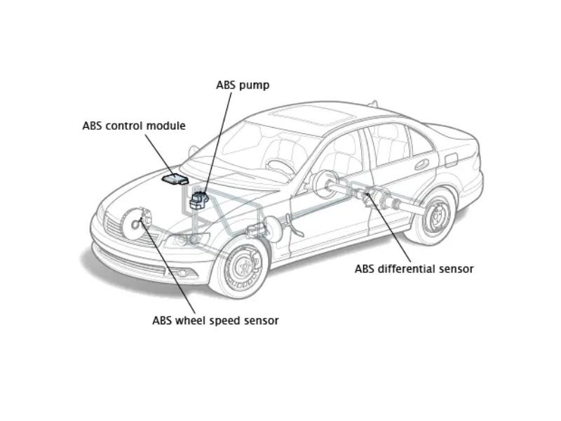
Wheel Speed Sensors
Wheel speed sensors form the foundation of ABS operation by providing critical speed data to the control module. These sensors typically use magnetic or optical technologies to detect wheel rotation. Magnetic sensors read metallic teeth on a tone ring attached to the wheel hub, generating electrical pulses proportional to wheel speed.
Modern vehicles often use active sensors that can detect wheel direction and provide more precise speed measurements. These sensors operate at lower speeds and provide better resolution for advanced ABS functions. Sensor placement varies by vehicle design, with some mounted in the wheel hub assembly and others positioned near the transmission or differential.
Common sensor failure modes include contamination from road debris, physical damage from impact, or electrical connection problems. ABS differential sensors in some systems monitor relative speed differences between wheels, providing additional data for traction control integration.
ABS Control Module (ECU)
The ABS control module serves as the system’s brain, processing input from multiple wheel speed sensors and making rapid decisions about brake pressure modulation. Modern control modules contain sophisticated microprocessors capable of complex calculations and predictive algorithms.
These units continuously monitor sensor inputs, comparing individual wheel speeds to vehicle speed and detecting patterns that indicate impending wheel lockup. The control module also performs self-diagnostic functions, monitoring system components and storing diagnostic trouble codes when problems are detected.
Integration with other vehicle systems allows the ABS control module to coordinate with traction control, electronic stability control, and brake assist systems. This integration enables more sophisticated vehicle dynamics management and improved overall safety performance.
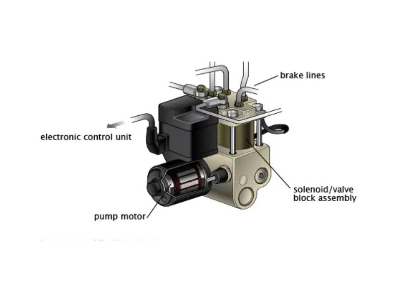
Hydraulic Control Unit (HCU)
The hydraulic control unit contains the valves, pumps, and accumulators necessary for brake pressure modulation. Solenoid-operated valves control brake fluid flow to individual wheels, enabling precise pressure control during ABS operation. These valves operate in milliseconds, ensuring rapid response to control module commands.
The electric pump motor maintains hydraulic pressure during ABS cycling, ensuring consistent brake performance throughout the modulation process. This pump also supports other systems like traction control and electronic stability control that require active brake pressure management.
Accumulator chambers store pressurized brake fluid, providing immediate pressure availability for rapid system response. The hydraulic control unit design varies by manufacturer, but all systems provide similar pressure modulation capabilities for effective ABS operation.
Brake Fluid Circuit Integration
ABS systems integrate seamlessly with conventional hydraulic brake circuits while adding pressure modulation capabilities. The master cylinder continues to provide primary brake pressure, with the ABS system modulating this pressure as needed for optimal wheel control.
Brake fluid quality becomes even more critical in ABS-equipped vehicles due to the system’s precise hydraulic requirements. Contaminated or degraded brake fluid can affect valve operation and sensor accuracy, potentially compromising ABS performance when it’s needed most.
Regular brake fluid service helps ensure optimal ABS operation and prevents internal component damage from moisture absorption or contamination. The increased complexity of ABS hydraulic circuits makes proper fluid maintenance essential for long-term system reliability.
Types of ABS Systems
Four-Channel, Four-Sensor Systems
Four-channel, four-sensor ABS systems provide individual wheel control and represent the most sophisticated ABS configuration. Each wheel has its own speed sensor and dedicated hydraulic control channel, enabling precise pressure modulation for optimal braking performance on each wheel independently.
This configuration offers superior performance on split-friction surfaces where different wheels encounter varying traction conditions. The system can apply different brake pressures to each wheel, maximizing stopping power while maintaining vehicle stability and steering control.
Most modern passenger vehicles use four-channel systems due to their superior performance characteristics and integration capabilities with electronic stability control and traction control systems. The additional complexity is offset by improved safety performance and more precise vehicle control.
Three-Channel, Three-Sensor Systems
Three-channel systems typically use individual sensors and control for the front wheels plus a shared channel for both rear wheels. This configuration provides good performance while reducing system complexity and cost compared to four-channel systems.
The shared rear channel means both rear wheels receive identical brake pressure modulation, which works well for most driving conditions but may be less optimal on split-friction surfaces. This design is common on pickup trucks and some SUVs where rear wheel control requirements are less critical.
Performance differences between three-channel and four-channel systems are minimal for most drivers under normal conditions. The choice often depends on vehicle design requirements, cost considerations, and integration with other safety systems.
Two-Channel, Four-Sensor Systems
Two-channel systems use four sensors but control brake pressure through two hydraulic channels, typically front and rear or left and right. This configuration provides good basic ABS functionality while maintaining reasonable system complexity.
Some systems use diagonal split configurations where each channel controls one front wheel and the opposite rear wheel. This design provides redundancy and maintains some braking capability even if one hydraulic circuit fails.
Two-channel systems are less common on modern vehicles but may be found on older vehicles or specialized applications where cost and simplicity are primary concerns.
Single-Channel Systems (Rear-Wheel Only)
Single-channel ABS systems typically control only the rear wheels and are found primarily on pickup trucks and some SUVs. These systems prevent rear wheel lockup, which can cause dangerous vehicle instability and loss of control.
While single-channel systems don’t provide the comprehensive control of multi-channel designs, they offer significant safety improvements over non-ABS vehicles, particularly in preventing rear-end skidding and maintaining vehicle stability during braking.
Modern vehicles rarely use single-channel ABS due to regulatory requirements and the minimal cost difference compared to more sophisticated systems. However, understanding these systems helps technicians work on older vehicles still in service.
Benefits of Anti-lock Braking Systems
Enhanced Vehicle Control
The primary benefit of ABS is maintaining steering control during emergency braking situations. Without ABS, locked wheels eliminate the driver’s ability to steer around obstacles, often leading to more severe accidents. ABS preserves tire traction, allowing drivers to steer while braking at maximum force.
This steering capability proves especially valuable in emergency situations where avoiding an obstacle may be more effective than attempting to stop before impact. Drivers can use full braking force while simultaneously steering around hazards, significantly improving accident avoidance capabilities.
Vehicle stability also improves with ABS, as the system prevents the rear-end sliding that often occurs when rear wheels lock during hard braking. This stability maintenance reduces the risk of spin-outs and loss of control, particularly important for inexperienced drivers who might otherwise panic and over-brake.
Reduced Stopping Distances on Various Surfaces
On most paved surfaces, ABS maintains or slightly reduces stopping distances compared to locked-wheel braking. The system’s ability to maintain optimal tire traction ensures maximum braking force transfer to the road surface. On wet or slippery surfaces, the stopping distance advantages become more pronounced.
However, on loose surfaces like gravel, sand, or deep snow, ABS may actually increase stopping distances compared to locked wheels that can dig into the surface material. Despite longer stopping distances, ABS maintains steering control, which is often more valuable for accident avoidance.
The key advantage lies in predictable, consistent braking performance across varying conditions. Drivers can apply maximum brake force without concern for wheel lockup, knowing the ABS system will optimize stopping power automatically.
Steering Capability During Emergency Braking
Maintaining steering capability during maximum braking represents ABS’s most significant safety contribution. Statistics show that many accidents could be avoided if drivers could steer while braking, making this capability potentially life-saving in emergency situations.
The psychological benefit of maintained steering control helps drivers remain calm during emergency braking situations. Rather than feeling helpless as the vehicle slides uncontrollably, drivers retain the ability to actively avoid obstacles or steer toward safer impact areas.
Training drivers to use ABS effectively includes emphasizing the importance of continuing to steer during emergency braking. Many drivers instinctively release the brakes when they feel ABS activation, reducing the system’s effectiveness.
Tire Wear Prevention
ABS prevents the severe tire wear associated with wheel lockup and skidding. Locked wheels that slide across pavement create flat spots and irregular wear patterns that can permanently damage tires and create vibration problems.
Even brief wheel lockup can create noticeable flat spots on tires, particularly on high-performance vehicles with softer tire compounds. ABS elimination of wheel lockup helps maintain even tire wear patterns and extends tire life significantly.
The cost savings from reduced tire wear often offset the additional complexity and maintenance costs associated with ABS systems. For fleet operators, these savings can be substantial over the life of the vehicles.
Integration with Other Safety Systems
Modern ABS systems provide the foundation for advanced safety technologies like electronic stability control (ESC), traction control, and brake assist systems. The wheel speed sensors and hydraulic control capabilities required for ABS enable these additional safety features with minimal additional hardware.
Electronic stability control systems use ABS components to selectively apply brakes to individual wheels, helping maintain vehicle stability during cornering and sudden maneuvers. This integration represents significant value for consumers and manufacturers.
Future safety technologies, including autonomous emergency braking and adaptive cruise control, rely heavily on ABS system components and capabilities. This makes ABS an essential foundation for advanced driver assistance systems becoming standard on new vehicles.
How ABS Systems Activate
Threshold Detection Process
ABS activation begins with the system’s continuous monitoring of wheel speeds through dedicated sensors. The control module compares individual wheel speeds to each other and to the calculated vehicle speed to identify wheels approaching lockup conditions.
The system establishes activation thresholds based on wheel deceleration rates rather than absolute speeds. When a wheel decelerates at a rate indicating impending lockup, the ABS control module initiates pressure modulation for that specific wheel.
Modern systems use sophisticated algorithms that consider factors like road surface conditions, vehicle loading, and brake application rate to optimize threshold settings. These adaptive capabilities help ensure appropriate ABS activation across varying driving conditions.
Rapid Pressure Cycling
Once activated, ABS systems cycle brake pressure multiple times per second to maintain optimal wheel slip ratios. The initial response typically involves rapid pressure release to allow the wheel to regain rotation, followed by controlled pressure reapplication.
The cycling rate varies based on conditions and system design, but typically ranges from 10-15 cycles per second. This rapid cycling creates the characteristic vibration and noise that drivers associate with ABS activation.
Pressure cycling continues until either the brake pedal is released or vehicle speed drops below the system’s minimum operating threshold. Most ABS systems deactivate at very low speeds where wheel lockup is less dangerous.
Driver Feedback (Pedal Pulsation)
The pulsating sensation drivers feel through the brake pedal during ABS activation results from the rapid pressure cycling within the hydraulic system. This feedback is intentional, alerting drivers that the ABS system is actively working to prevent wheel lockup.
Some drivers find the pedal pulsation alarming and instinctively reduce brake pressure or pump the brakes. However, maintaining steady, firm pressure on the brake pedal during ABS activation ensures optimal system performance.
Modern ABS systems may reduce pedal pulsation through improved hydraulic design and control algorithms, but some feedback remains to inform drivers of system activation. Understanding this feedback helps drivers use ABS systems more effectively.
System Deactivation Conditions
ABS systems automatically deactivate when vehicle speed drops below approximately 3-5 mph, as wheel lockup at very low speeds poses minimal danger. The system also deactivates when brake pressure is released or when the vehicle comes to a complete stop.
If the ABS system detects internal malfunctions, it may deactivate to prevent interference with normal braking operations. In this condition, the vehicle retains conventional braking capability, but without anti-lock protection.
System deactivation is typically indicated by warning lights on the vehicle dashboard. Drivers should seek professional diagnosis when ABS warning lights remain illuminated, as this indicates potential system problems.
Common Signs of ABS Problems
Dashboard Warning Light Activation
The ABS warning light serves as the primary indicator of system problems. This amber or yellow light, often labeled “ABS” or featuring a circular arrow symbol, illuminates when the system detects malfunctions or abnormal operating conditions.
Warning light activation can indicate various problems, from simple sensor contamination to serious hydraulic control unit failures. The light may illuminate continuously or intermittently, depending on the nature and severity of the problem.
Drivers should take ABS warning lights seriously, as they indicate loss of anti-lock protection. While normal braking typically remains functional, the safety benefits of ABS are not available until the problem is corrected.
Brake Pedal Behavior Changes
Changes in brake pedal feel or response can indicate ABS system problems. A spongy or soft pedal may suggest hydraulic issues within the ABS control unit, while unusual pedal travel could indicate valve problems or air in the system.
Some ABS problems cause the brake pedal to feel different during normal braking, even when the system isn’t actively cycling. These changes often indicate internal hydraulic problems that require professional diagnosis and repair.
Pedal pulsation during normal braking (when ABS shouldn’t be active) may indicate warped brake rotors, but can also suggest ABS valve problems or contamination within the hydraulic control unit.
Unusual Noises During Braking
ABS systems normally operate quietly except during active cycling when they may produce whirring, clicking, or buzzing sounds. Unusual noises during normal braking or constant noise from the ABS area may indicate motor problems or valve malfunctions.
Brake system noises can originate from various sources, making proper diagnosis important for identifying ABS-specific problems. Professional technicians use specialized equipment to isolate ABS-related noises from other brake system sounds.
Grinding or squealing during ABS activation may indicate problems with the hydraulic control unit or contaminated brake fluid affecting valve operation. These symptoms require prompt professional attention to prevent further system damage.
Increased Stopping Distances
While subtle changes in stopping distance can be difficult for drivers to detect, significant increases may indicate ABS problems affecting system performance. Malfunctioning ABS systems may not provide optimal brake pressure modulation, resulting in reduced braking effectiveness.
Comparing stopping distances requires consistent testing conditions, making this symptom challenging to identify without professional testing equipment. However, drivers who notice consistently longer stopping distances should have their brake systems inspected.
Other factors like worn brake pads, warped rotors, or tire problems can also affect stopping distances, making professional diagnosis essential for identifying the root cause of braking performance problems.
Steering Issues During Braking
ABS problems can affect vehicle stability and steering response during braking. A malfunctioning system may not prevent wheel lockup effectively, resulting in steering pull or loss of directional control during hard braking.
These symptoms become more noticeable during emergency braking situations when ABS should be most active. Drivers who experience unexpected steering behavior during braking should have their ABS systems inspected immediately.
Vehicle pulling during braking can also result from uneven brake wear, suspension problems, or tire issues. Professional diagnosis helps identify whether steering problems originate from the ABS system or other vehicle components.
ABS System Diagnosis and Testing
OBD-II Diagnostic Code Reading
Modern ABS systems store diagnostic trouble codes (DTCs) when malfunctions are detected. These codes provide valuable information about specific system problems and help technicians focus their diagnostic efforts efficiently.
Professional scan tools can access ABS-specific diagnostic codes that aren’t available through generic OBD-II readers. These specialized tools provide detailed information about sensor readings, valve operations, and system performance parameters.
Diagnostic codes should be interpreted in conjunction with symptom descriptions and system testing rather than relied upon exclusively. Some ABS problems may not generate codes, while others may produce multiple codes for a single underlying issue.
Wheel Speed Sensor Testing
Wheel speed sensor testing involves checking sensor output, wiring integrity, and physical condition. Technicians use oscilloscopes to verify proper sensor signal patterns and compare readings between different wheels.
Sensor contamination from metallic debris or brake dust can affect signal quality and trigger ABS problems. Physical inspection of sensors and tone rings helps identify contamination or damage that might not be apparent through electrical testing alone.
Resistance testing of sensor windings can identify internal sensor problems, while continuity testing verifies wiring integrity between sensors and the control module. These tests help isolate electrical problems within the ABS system.
Hydraulic System Pressure Tests
ABS hydraulic system testing requires specialized equipment to measure brake pressures during system operation. These tests verify proper valve operation and pump performance under various operating conditions.
Pressure testing can identify internal leakage within the hydraulic control unit, valve sticking problems, or pump motor malfunctions. These tests are essential for diagnosing ABS problems that don’t generate diagnostic codes.
Professional technicians use pressure transducers and oscilloscopes to monitor hydraulic pressure patterns during ABS cycling. This testing provides detailed information about system performance that isn’t available through other diagnostic methods.
Control Module Function Verification
ABS control module testing involves verifying proper response to sensor inputs and correct operation of output functions. Specialized diagnostic equipment can command individual valves and monitor system responses to verify control module operation.
Bidirectional scan tools allow technicians to activate ABS system components independently, enabling isolation of control module problems from sensor or hydraulic issues. This capability is essential for comprehensive ABS system diagnosis.
Control module replacement typically requires programming or calibration procedures to ensure proper integration with the specific vehicle. These procedures often require manufacturer-specific diagnostic equipment and software.
Maintenance Requirements for ABS
Regular Brake Fluid Changes
ABS systems place additional demands on brake fluid due to the increased complexity of hydraulic circuits and components. The precise tolerances within ABS valves make them more susceptible to contamination and moisture-related problems than conventional brake systems.
Moisture absorption in brake fluid can cause internal corrosion within ABS components and affect the precise hydraulic pressures required for optimal system operation. Regular fluid changes help prevent these problems and extend ABS system life.
Most manufacturers recommend brake fluid changes every 2-3 years for ABS-equipped vehicles, regardless of mileage. This interval may be shorter in severe operating conditions or climates with high humidity levels.
Sensor Cleaning and Inspection
ABS wheel speed sensors require periodic cleaning to remove accumulated brake dust, road debris, and metallic particles that can interfere with signal generation. Regular inspection helps identify physical damage or contamination before it affects system operation.
Sensor gap measurements ensure proper clearance between sensors and tone rings. Excessive gap due to wear or improper installation can reduce signal strength and cause intermittent ABS problems.
Tone ring inspection for damage, corrosion, or missing teeth helps identify mechanical problems that can cause sensor signal problems. These components are subject to road debris impact and corrosion that can affect ABS operation.
Electrical Connection Maintenance
ABS systems rely on numerous electrical connections that can be affected by corrosion, vibration, and environmental exposure. Regular inspection of connectors and wiring helps identify potential problems before they cause system failures.
Connector cleaning and dielectric grease application help prevent corrosion in electrical connections exposed to road salt and moisture. This maintenance is particularly important in harsh climates where corrosion problems are common.
Wiring inspection for damage from road debris, heat exposure, or abrasion helps identify potential short circuits or open circuits that can cause ABS malfunctions. Early identification prevents more extensive electrical problems.
System Performance Monitoring
Regular test drives that include various braking scenarios help identify subtle changes in ABS performance before they become serious problems. Drivers familiar with their vehicle’s normal ABS operation can often detect changes that indicate developing problems.
Professional ABS system testing during regular brake service helps identify problems that might not be apparent during normal driving. This testing can reveal issues with sensor accuracy, hydraulic performance, or control module operation.
Keeping records of ABS service and any problems helps identify patterns that might indicate recurring issues or component reliability problems. This information assists technicians in diagnosing intermittent problems.
ABS vs. Other Brake Technologies
Electronic Stability Control (ESC) Integration
Electronic Stability Control systems build upon ABS technology by adding yaw sensors, lateral acceleration sensors, and steering angle sensors to monitor vehicle dynamics. ESC uses the ABS hydraulic control unit to apply brakes selectively to individual wheels, helping maintain vehicle stability during cornering and emergency maneuvers.
The integration between ABS and ESC represents a natural evolution of brake technology, with both systems sharing sensors, hydraulic components, and control modules. This integration provides comprehensive vehicle dynamics control while minimizing additional hardware costs.
ESC systems can intervene even when the driver isn’t applying the brakes, using ABS components to apply corrective braking forces automatically. This capability significantly enhances vehicle safety beyond what ABS alone can provide.
Traction Control System Coordination
Traction control systems use ABS wheel speed sensors and hydraulic components to prevent drive wheel spin during acceleration. When sensors detect wheel spin, the system applies brake pressure to the spinning wheel, transferring power to wheels with better traction.
The coordination between ABS and traction control enables seamless operation during changing driving conditions. Both systems use similar sensor inputs and hydraulic controls, making integration logical and cost-effective for manufacturers.
Advanced traction control systems can also reduce engine power in addition to applying brakes, providing more sophisticated wheel spin control. This engine management integration requires coordination between the ABS control module and engine management systems.
Brake Assist System Interaction
Brake assist systems detect emergency braking situations and automatically apply maximum brake force to help drivers achieve optimal stopping performance. These systems use ABS components to monitor brake application rate and apply additional hydraulic pressure when needed.
The interaction between brake assist and ABS ensures that maximum braking force is applied without causing wheel lockup. This coordination provides optimal stopping performance while maintaining vehicle control during emergency situations.
Some brake assist systems can detect obstacles and apply brakes automatically, representing the beginning of autonomous emergency braking technology. These systems rely heavily on ABS components for their operation.
Regenerative Braking in Hybrid/Electric Vehicles
Hybrid and electric vehicles use regenerative braking to recover energy during deceleration, requiring sophisticated coordination with ABS systems. The transition between regenerative and friction braking must be seamless to maintain consistent pedal feel and braking performance.
ABS systems in hybrid vehicles must account for the additional complexity of regenerative braking while maintaining anti-lock functionality. This requires more sophisticated control algorithms and integration between multiple vehicle systems.
The future of braking technology will likely involve even greater integration between regenerative systems, ABS, and autonomous driving technologies. Understanding current ABS operation provides a foundation for working with these emerging technologies.
Troubleshooting Common ABS Issues
Sensor Malfunction Diagnosis
ABS sensor problems represent the most common cause of system malfunctions. Diagnostic procedures typically begin with reading stored trouble codes, followed by physical inspection of sensors and wiring. Visual inspection often reveals contamination, physical damage, or improper installation that affects sensor operation.
Electrical testing of sensor circuits includes resistance measurements, signal voltage testing, and wiring continuity verification. Oscilloscope testing provides detailed information about sensor signal quality and helps identify intermittent problems that might not be apparent through basic electrical testing.
Sensor gap measurements ensure proper clearance between sensors and tone rings. Incorrect gaps due to improper installation or component wear can cause weak signals that may not register properly with the control module.
Hydraulic System Problems
ABS hydraulic problems can range from simple contamination issues to complete hydraulic control unit failure. Symptoms may include spongy brake pedal feel, unusual noises during braking, or loss of ABS function accompanied by warning light activation.
Brake fluid contamination affects the precise hydraulic pressures required for ABS operation. Moisture contamination can cause internal corrosion, while particulate contamination can cause valve sticking or poor sealing within the hydraulic control unit.
Hydraulic pressure testing requires specialized equipment and should only be performed by qualified technicians. These tests can identify internal leakage, valve problems, or pump motor malfunctions that affect ABS performance.
Control Module Failure Signs
ABS control module problems often manifest as multiple simultaneous symptoms or erratic system behavior. The module may generate multiple diagnostic codes, fail to respond to scan tool commands, or cause the ABS system to activate inappropriately.
Control module diagnosis requires specialized scan tools capable of communicating with ABS systems and commanding individual system components. These tools can verify proper module operation and identify internal failures that require module replacement.
Replacement control modules often require programming or calibration procedures specific to the individual vehicle. These procedures ensure proper integration with other vehicle systems and optimal ABS performance.
When to Seek Professional Service
ABS system complexity makes professional diagnosis essential for most problems beyond basic maintenance. The specialized equipment and training required for proper ABS service are typically available only at qualified service facilities.
Safety considerations make professional service particularly important for ABS problems. Improper brake system work can result in brake failure and serious accidents, making qualified technician involvement essential for any significant ABS repairs.
The integration between ABS and other vehicle safety systems means that ABS problems can affect multiple systems simultaneously. Professional technicians have the tools and knowledge necessary to diagnose these complex interactions properly.
Safety Considerations and Best Practices
Proper ABS Operation Techniques
Understanding proper ABS operation helps drivers use the system effectively during emergency situations. The most important technique is maintaining firm, steady pressure on the brake pedal during ABS activation rather than pumping the brakes or reducing pressure when pedal pulsation occurs.
Drivers should expect and become familiar with the normal sounds and sensations associated with ABS activation. The characteristic pedal pulsation and system noises are normal and indicate that the system is working properly to prevent wheel lockup.
Steering input remains important during ABS activation, as the system maintains steering capability that would be lost with locked wheels. Drivers should continue to steer around obstacles while maintaining maximum brake pressure during emergency stops.
Emergency Braking Procedures
Effective emergency braking with ABS involves applying maximum brake force immediately while simultaneously steering to avoid obstacles. Unlike vehicles without ABS, there’s no need to modulate brake pressure or pump the brakes during emergency stops.
The key to effective ABS use is overcoming the natural tendency to reduce brake pressure when the system activates. Many drivers instinctively pump the brakes or reduce pressure when they feel pedal pulsation, reducing the system’s effectiveness.
Practice in safe environments helps drivers become comfortable with ABS operation and improves their ability to use the system effectively during actual emergencies. Understanding system capabilities and limitations builds confidence in emergency situations.
System Limitations and Conditions
ABS systems have limitations that drivers should understand for optimal safety. The system cannot overcome the basic laws of physics and won’t necessarily reduce stopping distances on all surface types. On loose surfaces like gravel or sand, ABS may actually increase stopping distances while maintaining steering control.
Weather conditions affect ABS performance, with ice and snow presenting particular challenges. While ABS maintains steering capability, drivers must adjust their driving to account for reduced traction and longer stopping distances on slippery surfaces.
Vehicle maintenance affects ABS performance, with worn tires, contaminated brake fluid, or damaged suspension components potentially reducing system effectiveness. Regular maintenance helps ensure optimal ABS performance when it’s needed most.
Professional Inspection Importance
Regular professional brake system inspections help identify potential ABS problems before they cause system failures. Qualified technicians can perform diagnostic tests and maintenance procedures that aren’t possible with basic tools and equipment.
The complexity of modern ABS systems makes professional diagnosis essential for most problems. Attempting to repair ABS systems without proper training and equipment can result in brake system problems that compromise vehicle safety.
Professional service ensures that ABS repairs meet manufacturer specifications and safety standards. This is particularly important given the safety-critical nature of brake systems and the potential consequences of improper repairs.
Important Safety Reminder: This information is provided for educational purposes only. Always consult qualified brake system technicians for ABS diagnosis, repair, and maintenance. Improper brake system work can result in brake failure and serious accidents. When in doubt, seek professional assistance through our contact form or reach qualified service providers in your area.
For additional technical resources and service manuals, visit our Vehicle Systems & Parts Explained section or explore our comprehensive brake system resources. Professional technicians can access detailed service information through our technical manual library to ensure proper ABS system service and repair procedures.