The ABS wheel speed sensor stands as one of your vehicle’s most critical safety components, yet many drivers remain unaware of its vital role until something goes wrong. When an ABS wheel speed sensor fails, your vehicle loses a crucial layer of braking protection, potentially compromising your safety during emergency stops. Understanding how to identify problems, perform diagnostics, and address issues can mean the difference between maintaining optimal braking performance and facing dangerous situations on the road.
This comprehensive guide explores everything you need to know about ABS wheel speed sensors, from basic operation principles to advanced diagnostic procedures. Whether you’re a DIY enthusiast looking to expand your automotive knowledge or a professional technician seeking detailed repair procedures, this technical resource provides the expertise you need to handle ABS sensor issues safely and effectively.
What Is an ABS Wheel Speed Sensor?
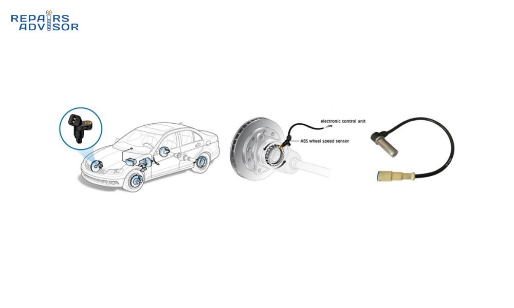
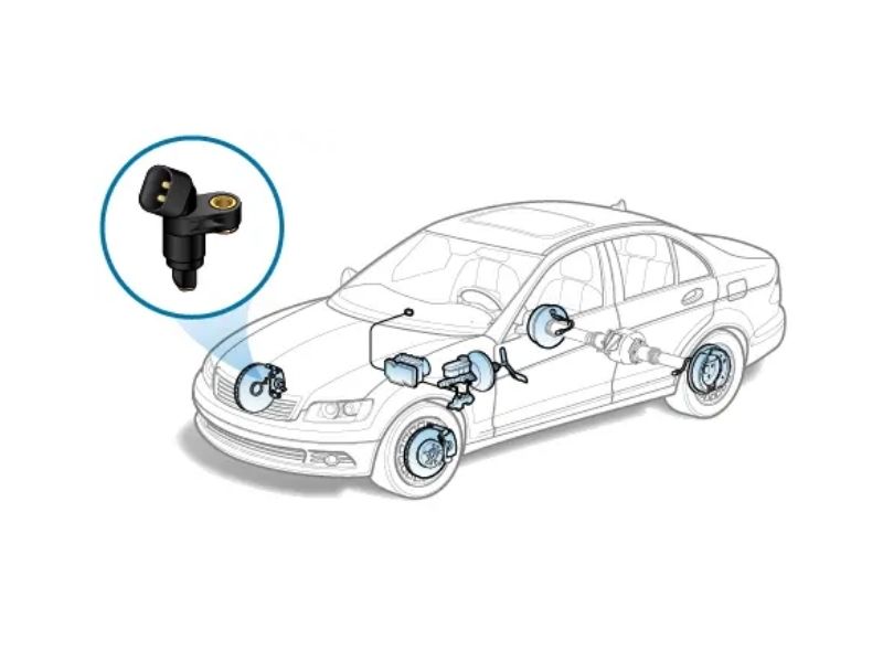
An ABS wheel speed sensor is a sophisticated electronic component that monitors the rotational speed of each wheel and transmits this critical information to your vehicle’s Anti-lock Braking System (ABS): Why It Is Important and How It Works. These sensors serve as the eyes and ears of your ABS system, continuously measuring wheel rotation speed and detecting when a wheel begins to lock up during braking.
The sensor works in conjunction with the ABS Control Module: The Brains Behind Your Safe Stops to prevent wheel lockup, maintain steering control, and optimize stopping distances. Without properly functioning wheel speed sensors, your ABS system cannot perform its life-saving function of modulating brake pressure during emergency stops.
How ABS Wheel Speed Sensors Work
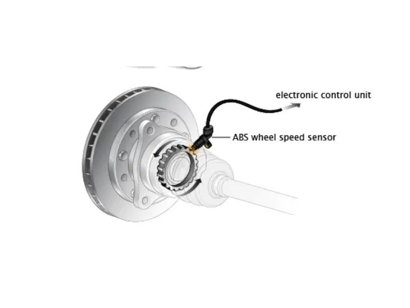
ABS wheel speed sensors operate on the principle of electromagnetic induction, generating electrical signals based on the rotation of a toothed ring or reluctor wheel attached to each wheel hub. As the wheel rotates, the sensor detects the passing of each tooth on the reluctor ring, creating a pulsing electrical signal that corresponds directly to wheel speed.
The sensor generates this signal through one of two primary methods. In passive sensors, a permanent magnet and coil assembly creates a varying magnetic field as the reluctor ring teeth pass by, inducing an alternating current voltage signal. Active sensors use a Hall effect sensor or magnetoresistive element powered by the vehicle’s electrical system to detect magnetic field changes and generate a more precise digital signal.
The frequency of these electrical pulses directly correlates to wheel speed – the faster the wheel rotates, the higher the pulse frequency. This signal travels instantly to the ABS control module, which compares the speed of all four wheels multiple times per second. When the module detects a significant speed difference between wheels, indicating potential lockup, it commands the ABS Pump: The “Extra Push” for Your Brakes to modulate brake pressure and prevent wheel lockup.
Types of ABS Wheel Speed Sensors
Modern vehicles use two primary types of ABS wheel speed sensors, each with distinct characteristics and applications. Understanding the differences between sensor types is crucial for proper diagnosis and replacement.
Active sensors, also known as Hall effect sensors, require power from the vehicle’s electrical system to operate. These sensors provide more accurate readings at low speeds and can detect wheel rotation direction, making them essential for advanced systems like electronic stability control and hill start assist. Active sensors typically generate a square wave digital signal and are commonly found on newer vehicles with sophisticated ABS and stability control systems.
Passive sensors, or magnetic pickup sensors, generate their own electrical signal through electromagnetic induction without requiring external power. These sensors are simpler in design and more robust in harsh conditions but cannot detect wheel rotation at very low speeds or determine rotation direction. Passive sensors produce a sinusoidal analog signal and are typically found on older vehicles or basic ABS systems.
Sensor location varies depending on vehicle design and drivetrain configuration. Front-wheel sensors are commonly mounted in the steering knuckle or brake caliper bracket, positioned close to the reluctor ring on the CV joint or wheel hub. Rear sensors may be located in the rear axle housing, brake backing plate, or suspension components, depending on whether the vehicle has independent or solid rear suspension.
Common Signs of a Bad ABS Wheel Speed Sensor
Recognizing the symptoms of a failing ABS wheel speed sensor is crucial for maintaining your vehicle’s safety systems. Early detection allows for proactive repair before complete sensor failure compromises your braking performance. The symptoms often develop gradually, starting as intermittent issues that become more frequent and severe over time.
Dashboard Warning Lights
The most obvious indicator of ABS wheel speed sensor problems is illumination of warning lights on your vehicle’s dashboard. The ABS warning light activation serves as your primary alert system that something is wrong with the anti-lock braking system. This amber or yellow light typically appears as “ABS” text or a circular symbol with “ABS” lettering, and its activation indicates the ABS system has detected a fault and may have disabled itself as a safety precaution.
Modern vehicles often display multiple warning lights simultaneously when wheel speed sensor issues occur. The traction control system warning light frequently accompanies ABS warnings because both systems rely on wheel speed sensor data to function properly. Electronic stability control (ESC) systems also depend on accurate wheel speed information, so ESC warning lights may illuminate alongside ABS indicators.
Some vehicles provide more specific diagnostic information through the instrument cluster, displaying messages like “ABS Service Required,” “Traction Control Off,” or “Stability System Fault.” These messages indicate that the vehicle’s onboard diagnostic system has detected wheel speed sensor circuit problems and may have stored specific diagnostic trouble codes for professional analysis.
Performance Symptoms
Beyond warning lights, failing ABS wheel speed sensors create noticeable changes in your vehicle’s braking performance and handling characteristics. These physical symptoms often provide the clearest indication of sensor problems and help differentiate between ABS issues and other brake system problems.
Wheel lockup during braking represents the most serious performance symptom of ABS wheel speed sensor failure. When a sensor cannot provide accurate speed data, the ABS system cannot detect impending wheel lockup and fails to modulate brake pressure accordingly. This results in wheels locking up during hard braking, causing loss of steering control and increased stopping distances, particularly on slippery surfaces.
Loss of ABS functionality during emergency stops becomes evident when you feel the brake pedal behavior change during panic braking situations. Normally, ABS activation creates a pulsing sensation in the brake pedal and may produce grinding or chattering sounds as the system rapidly modulates brake pressure. When wheel speed sensors fail, this protective pulsing action disappears, and the pedal feels firm and unresponsive during lockup conditions.
Vehicle pulling during braking can indicate problems with wheel speed sensors, particularly when the pulling occurs inconsistently or varies with braking intensity. Inaccurate speed readings from a faulty sensor can cause the ABS system to apply incorrect brake pressure modulation, resulting in uneven braking forces that pull the vehicle to one side.
Diagnostic Trouble Codes
Modern vehicles store specific diagnostic trouble codes when wheel speed sensor problems occur, providing technicians with precise information about the nature and location of sensor faults. These codes serve as roadmaps for efficient diagnosis and repair of ABS wheel speed sensor issues.
Common wheel speed sensor codes include C0031 for left front sensor circuit problems, which you can learn more about in our detailed Code C0031 – Left Front Wheel Speed Sensor Circuit analysis. Similar codes exist for each wheel position, with C0032 for right front, C0035 for left rear, and C0036 for right rear wheel speed sensors.
The diagnostic trouble code system provides specific information about the type of sensor failure. Circuit continuity codes indicate broken wires or poor connections, while signal range codes suggest sensor contamination, air gap problems, or internal sensor failures. Rationality codes appear when one sensor provides readings that differ significantly from other wheel speed sensors, indicating potential mechanical damage or incorrect installation.
Professional diagnostic equipment can retrieve these codes and provide additional information about sensor performance, including live data streams showing real-time wheel speed readings. Understanding these diagnostic codes helps determine whether sensor replacement is necessary or if cleaning and adjustment might resolve the problem. For a comprehensive list of chassis-related diagnostic codes, refer to our List of All C Codes (Chassis) – OBD2 resource.
Professional Diagnostic Procedures
Proper diagnosis of ABS wheel speed sensor problems requires systematic testing procedures and appropriate diagnostic equipment. Professional diagnosis ensures accurate problem identification and prevents unnecessary part replacement, saving both time and money while maintaining repair quality standards.
Required Tools and Equipment
Successful ABS wheel speed sensor diagnosis demands specific tools and equipment capable of measuring electrical signals and analyzing sensor performance. An OBD-II scanner with ABS capability represents the minimum diagnostic tool requirement, providing access to diagnostic trouble codes, live data streams, and system reset functions necessary for comprehensive sensor analysis.
A digital multimeter with high impedance input is essential for electrical testing of wheel speed sensors and their associated circuits. The multimeter must be capable of measuring AC voltage, DC voltage, and resistance with sufficient accuracy to detect subtle sensor problems. Look for meters with min/max functions and data logging capabilities to capture intermittent sensor faults that occur only under specific driving conditions.
Professional diagnosis often requires oscilloscope capabilities to analyze sensor signal patterns and detect waveform abnormalities that standard multimeters cannot identify. USB-based automotive oscilloscopes provide cost-effective access to advanced signal analysis features, allowing technicians to observe sensor output patterns under various operating conditions and compare normal versus abnormal signal characteristics.
Additional specialized tools enhance diagnostic accuracy and efficiency. Breakout boxes allow safe connection to sensor circuits without damaging connectors or wiring. Test lights with high impedance prevent damage to sensitive electronic circuits during continuity testing. For comprehensive diagnostic capabilities, explore our Tools & Equipment – Repairs Advisor Blog section for detailed equipment recommendations.
Step-by-Step Diagnostic Process
Professional ABS wheel speed sensor diagnosis follows a systematic approach that progresses from simple visual inspection to advanced electrical testing. This methodology ensures thorough problem identification while minimizing diagnostic time and preventing overlooked issues that could cause repeat failures.
Visual inspection forms the foundation of effective sensor diagnosis. Begin by examining each wheel speed sensor and its associated wiring for obvious damage, contamination, or corrosion. Remove wheels if necessary to access sensors mounted in brake components or suspension systems. Look for damaged sensor tips, bent mounting brackets, contaminated reluctor rings, or excessive air gaps between sensors and reluctor wheels.
Inspect sensor wiring harnesses thoroughly, paying particular attention to areas where wires flex during steering or suspension movement. Check for chafed insulation, broken conductors, corroded connections, or damaged connectors. Use a test light or multimeter to verify power and ground connections at sensor connectors, ensuring voltage levels match manufacturer specifications.
Electrical testing begins with resistance measurements of sensor coils in passive sensors or power supply verification in active sensors. Compare resistance readings between sensors of the same type, as significant variations often indicate internal sensor damage. For active sensors, verify proper power supply voltage and ground connections using manufacturer specifications.
Signal testing requires connecting diagnostic equipment while operating the vehicle under controlled conditions. Use live data functions to observe wheel speed readings during acceleration, deceleration, and turning maneuvers. Compare readings between all four wheels, looking for erratic signals, missing data, or readings that don’t correlate with actual wheel movement.
Safety Protocols During Diagnosis
Safety considerations during ABS wheel speed sensor diagnosis cannot be overstated because the procedures involve working around brake systems, electrical circuits, and moving vehicle components. Proper safety protocols protect both technicians and vehicles from injury or damage during diagnostic procedures.
Vehicle securing procedures must be followed religiously when performing sensor diagnosis that requires wheel removal or vehicle movement. Use appropriate jack stands rated for the vehicle’s weight, never relying solely on hydraulic jacks for support. When diagnosis requires running the vehicle with wheels removed, use proper axle stands and ensure no personnel are positioned where rotating components could cause injury.
Electrical safety measures prevent damage to sensitive ABS components during testing procedures. Never use conventional test lights or circuit testers on ABS circuits, as these tools can draw excessive current and damage electronic components. Always disconnect the battery when working on sensor connections to prevent accidental short circuits or unexpected ABS system activation.
Brake system precautions ensure that diagnostic procedures don’t compromise braking safety. Never disconnect brake components or drain brake fluid unnecessarily during sensor diagnosis. If ABS system bleeding becomes necessary after sensor replacement, follow proper bleeding procedures to prevent air introduction into the brake hydraulic system.
ABS Wheel Speed Sensor Replacement Guide
ABS wheel speed sensor replacement requires careful attention to detail and proper procedures to ensure reliable operation and prevent premature failure. Professional replacement techniques extend sensor life and maintain system performance while avoiding common installation mistakes that cause repeat failures.
Pre-Replacement Preparation
Proper preparation sets the foundation for successful sensor replacement and helps avoid complications during the installation process. Begin by identifying the exact replacement sensor required for your specific vehicle, as sensors vary significantly between different makes, models, and production years. Verify part numbers match exactly, as even minor differences in connector types, mounting configurations, or electrical specifications can cause compatibility problems.
Parts identification and sourcing requires attention to sensor type and specifications. Determine whether your vehicle uses active or passive sensors, as replacement procedures and specifications differ between types. Active sensors require careful handling to prevent damage to internal electronics, while passive sensors need specific air gap settings for proper operation. Source replacement sensors from reputable suppliers who can verify compatibility and provide technical support if installation questions arise.
Tool preparation checklist should include all equipment needed for safe and efficient replacement. Basic hand tools, including metric socket sets, screwdrivers, and pliers, handle most sensor mounting hardware. Specialized tools may include pick sets for connector release tabs, wire terminal tools for harness repair, and torque wrenches for proper mounting bolt installation. Gather cleaning supplies to remove contamination from sensor mounting areas and reluctor ring surfaces.
Safety equipment requirements include protective gear and vehicle support equipment. Safety glasses protect eyes from debris during cleaning procedures, while work gloves prevent cuts from sharp metal edges around brake components. Ensure proper vehicle lifting equipment is available and functional before beginning work, as sensor replacement often requires wheel removal and access to suspension components.
Removal Procedures
Sensor removal procedures vary significantly depending on sensor location and vehicle design, but certain principles apply universally to prevent damage during disassembly. Begin by disconnecting the vehicle’s battery to prevent accidental ABS system activation or electrical shorts during connector manipulation. Remove wheels to access sensors mounted in brake components or suspension systems, taking care to support the vehicle properly throughout the process.
Access panel removal may be necessary for sensors located in protected areas of the vehicle. Some sensors mount inside wheel wells behind plastic access panels, while others require removal of brake components or suspension parts for access. Follow manufacturer procedures for component removal, keeping track of fastener locations and orientations to ensure proper reassembly.
Sensor disconnection steps require careful handling of electrical connectors to prevent damage to fragile plastic components or delicate electrical contacts. Release connector locking tabs using appropriate tools, avoiding excessive force that could break connector housings. If connectors appear corroded or difficult to separate, apply appropriate electrical contact cleaner and allow penetration time before attempting removal.
Mounting hardware extraction demands attention to sensor positioning and surrounding components. Note sensor orientation and mounting depth before removal, as improper installation can cause air gap problems or mechanical interference. Remove mounting bolts using appropriate tools, taking care not to drop hardware into inaccessible areas. If sensors appear seized in their mounting holes, apply penetrating lubricant and allow time for penetration before using extraction force.
Installation Best Practices
Proper sensor positioning ensures optimal performance and prevents premature failure due to mechanical interference or incorrect air gap settings. Clean sensor mounting holes thoroughly, removing all dirt, corrosion, or old sealant that could prevent proper sensor seating. Inspect reluctor ring surfaces and clean if necessary, as contamination can interfere with sensor operation even after successful installation.
Install replacement sensors using manufacturer-specified procedures and torque values. Apply thread locking compound to mounting bolts if specified, ensuring proper thread engagement without cross-threading. Position sensors at the correct depth and orientation, referring to service manual specifications or measurements taken during removal. Avoid forcing sensors into mounting holes, as excessive pressure can damage sensor housings or mounting threads.
Electrical connection procedures require attention to connector orientation and sealing. Ensure connectors are clean and dry before mating, applying dielectric grease to contact surfaces if specified by the manufacturer. Press connectors together firmly until locking tabs engage completely, verifying secure connection by gently pulling on the connector body. Route sensor wiring away from heat sources, moving components, and sharp edges that could cause chafing or damage.
Air gap specifications are critical for passive sensor operation and must be set according to manufacturer requirements. Use appropriate feeler gauges to measure the gap between sensor tips and reluctor ring teeth, adjusting sensor position as necessary to achieve proper clearance. Active sensors typically don’t require air gap adjustment but must be positioned to maintain proper clearance from rotating components throughout the full range of suspension movement.
Post-Installation Testing
System reset procedures are essential after ABS wheel speed sensor replacement to ensure proper system operation and clear any stored diagnostic codes. Connect a professional OBD-II scanner with ABS capabilities and clear all stored fault codes from the ABS control module. Some vehicles require specific initialization procedures or adaptation routines to properly recognize new sensors and calibrate the system for optimal performance.
Road test protocols verify sensor operation under actual driving conditions and confirm that installation procedures were completed correctly. Begin with low-speed testing in a safe area, observing ABS warning lights and monitoring system operation through diagnostic equipment if available. Gradually increase speed and test various driving conditions, including acceleration, deceleration, and turning maneuvers to verify sensors provide consistent readings.
Diagnostic verification confirms that sensor replacement has resolved the original problem and that no additional issues exist. Use live data functions to observe wheel speed sensor readings during road testing, verifying that all sensors provide consistent and accurate data. Compare readings between wheels to ensure no significant variations exist that could indicate installation problems or additional sensor failures.
Final system check should include verification that all ABS functions operate properly. Test ABS activation on appropriate surfaces using controlled braking techniques, feeling for proper system engagement and pedal pulsation. Verify that warning lights remain off during normal operation and that traction control and stability systems function as designed.
Preventive Maintenance and Care
Preventive maintenance significantly extends ABS wheel speed sensor life and prevents unexpected failures that could compromise vehicle safety. Regular maintenance procedures cost far less than emergency repairs and help identify potential problems before they cause system failures or safety hazards.
Regular Inspection Schedule
Visual inspection intervals should coincide with regular brake service or tire rotation procedures to maximize efficiency and ensure comprehensive system monitoring. During routine maintenance, examine sensor mounting areas for signs of damage, contamination, or corrosion that could affect sensor operation. Look for loose mounting hardware, damaged wiring, or contamination buildup that could interfere with sensor-to-reluctor ring clearances.
Cleaning procedures help prevent contamination-related sensor failures that account for a significant percentage of premature sensor problems. Use appropriate brake cleaner or electrical contact cleaner to remove dirt, grease, and metallic particles from sensor tips and reluctor ring surfaces. Avoid using harsh chemicals or abrasive materials that could damage sensor housings or reluctor ring teeth.
Environmental protection measures extend sensor life in harsh operating conditions. Apply dielectric grease to electrical connections to prevent moisture intrusion and corrosion. Consider protective coating application in areas exposed to road salt or chemical contamination. Ensure proper routing of sensor wiring to prevent damage from road debris or component movement.
Comprehensive brake system maintenance supports ABS sensor longevity by maintaining proper brake component operation and preventing contamination from failed brake parts. Follow recommended brake fluid change intervals, as contaminated brake fluid can cause corrosion throughout the brake system. For detailed brake maintenance procedures, refer to our guide on How to Bleed Your Brakes: A Professional Step-by-Step Guide.
Common Causes of Sensor Failure
Road debris and contamination represent the leading causes of premature ABS wheel speed sensor failure in most driving conditions. Metal particles from brake pad wear, road salt, and accumulated dirt can interfere with sensor operation or cause physical damage to sensor components. Regular cleaning and inspection help identify contamination problems before they cause complete sensor failure.
Corrosion and moisture exposure particularly affect sensor electrical connections and wiring harnesses. Water intrusion into electrical connectors causes corrosion that increases electrical resistance and creates intermittent connection problems. Damaged wire insulation allows moisture to reach conductors, causing corrosion and eventual circuit failure. Pay special attention to areas where wiring harnesses pass through body panels or areas exposed to road spray.
Mechanical damage factors include impact damage from road debris, improper installation procedures, and normal wear from vehicle operation. Sensors mounted in exposed locations are particularly vulnerable to damage from rocks, debris, or contact with road surfaces during off-road driving. Improper installation can cause sensor damage from overtightening, incorrect positioning, or interference with moving components.
Age-related sensor degradation affects both active and passive sensor types through different mechanisms. Passive sensors experience gradual loss of magnetic strength and coil deterioration over time. Active sensors can suffer from electronic component failure, moisture intrusion into sealed housings, or degradation of Hall effect elements. Understanding these aging mechanisms helps predict sensor replacement intervals and plan preventive maintenance schedules.
When to Seek Professional Help
Recognizing the limits of DIY repair capabilities ensures safety and prevents costly mistakes during ABS wheel speed sensor service. Professional assistance becomes essential when diagnostic complexity exceeds available tools or expertise, particularly for vehicles with advanced ABS systems or integrated stability control features.
Complex diagnostic scenarios requiring professional expertise include intermittent sensor problems that don’t produce consistent symptoms or diagnostic codes. Professional diagnostic equipment can capture elusive faults through extended monitoring and advanced signal analysis capabilities not available with basic OBD-II scanners. Multiple sensor failures or system-wide ABS problems often indicate more complex issues requiring comprehensive system analysis.
Specialized tool requirements may necessitate professional service when sensor replacement procedures require equipment beyond typical DIY capabilities. Some sensors require special removal tools, calibration procedures, or programming sequences that demand professional diagnostic equipment. Vehicles with integrated ABS and stability control systems may need specific initialization procedures available only through manufacturer diagnostic tools.
Safety-critical system concerns make professional service advisable for individuals lacking experience with brake system components or ABS diagnostics. Improper sensor installation or incomplete system bleeding can create safety hazards that far outweigh potential cost savings from DIY repair attempts. When in doubt, consult qualified technicians who can ensure proper repair procedures and system functionality.
For additional vehicle care guidance and maintenance tips, explore our comprehensive Vehicle Care Tips section. If you need specific technical information for your vehicle, our extensive collection of service manuals provides detailed procedures and specifications for professional-quality repairs.
Cost Considerations and Planning
Understanding the financial aspects of ABS wheel speed sensor replacement helps vehicle owners make informed decisions about repair timing and service options. Cost planning allows for proactive maintenance that prevents more expensive emergency repairs and ensures continued vehicle safety.
Typical sensor replacement costs vary significantly based on vehicle make, model, and sensor location accessibility. Basic passive sensors for common domestic vehicles typically cost between $25-75 per sensor, while advanced active sensors for luxury or import vehicles can range from $75-200 or more. Labor costs depend on sensor location and accessibility, with simple replacements requiring 0.5-1.0 hours per sensor, while difficult-to-access sensors may require 2-3 hours of labor.
Labor time estimates increase significantly when sensor replacement requires suspension component removal, brake system bleeding, or extensive diagnostic procedures to identify intermittent faults. Factor additional time for proper system testing and initialization procedures that ensure reliable sensor operation after installation.
OEM versus aftermarket sensor considerations affect both initial cost and long-term reliability. OEM sensors typically provide exact fit and finish with proven durability but cost significantly more than aftermarket alternatives. Quality aftermarket sensors offer substantial cost savings while maintaining adequate performance for most applications. Avoid extremely low-cost sensors that may fail prematurely and require repeated replacement.
Sensor replacement strategy should consider maintenance efficiency and cost-effectiveness. Labor costs for accessing and replacing multiple sensors simultaneously are often less per sensor than individual replacement procedures. Consult with qualified technicians to determine the most cost-effective approach based on your vehicle’s specific condition and sensor accessibility.
Safety Notice: This information is provided for educational purposes only. ABS wheel speed sensor replacement involves working with critical safety systems that require proper procedures and specialized knowledge. Always consult qualified technicians for complex diagnostic procedures or when safety concerns exist. Improper installation or incomplete system testing can create safety hazards that compromise vehicle braking performance.
For additional technical support or specific vehicle information, contact our technical team at [email protected] or visit our help center for comprehensive repair resources and professional guidance.
Related ABS System Components:
- Signs Your ABS Valve Assembly Is Failing
- ABS Differential Sensor: Sensing Your Speed
- Signs Your Brake Booster Is Failing: Getting That Extra Push
Advanced Troubleshooting Techniques
Professional ABS wheel speed sensor diagnosis often requires advanced troubleshooting techniques that go beyond basic code reading and visual inspection. These advanced methods help identify intermittent problems and complex system interactions that standard diagnostic procedures might miss.
Signal Pattern Analysis
Oscilloscope analysis provides the most detailed view of sensor performance by displaying actual signal waveforms generated during wheel rotation. Connect the oscilloscope to sensor output circuits while rotating wheels manually or during low-speed driving to observe signal characteristics. Normal passive sensor signals display clean sinusoidal waveforms with consistent amplitude and frequency, while faulty sensors show distorted patterns, amplitude variations, or signal dropouts.
Active sensor analysis requires different techniques because these sensors produce digital square wave signals rather than analog sinusoidal outputs. Use oscilloscope edge triggering to capture clean digital transitions and measure signal timing accuracy. Look for missing pulses, incorrect voltage levels, or timing irregularities that indicate sensor or reluctor ring problems.
Comparative analysis between sensors helps identify subtle problems that might not be apparent when examining individual sensors. Display multiple sensor outputs simultaneously on a multi-channel oscilloscope, comparing signal amplitude, frequency, and timing relationships during identical wheel rotation speeds. Significant variations between sensors of the same type often indicate developing problems before they cause complete system failure.
Temperature-Related Diagnostics
Temperature variations significantly affect ABS sensor performance, particularly in passive sensors where coil resistance changes with temperature. Conduct diagnostic tests at different operating temperatures to identify sensors that fail when hot or cold. Some sensors work correctly when cold but fail after extended driving when components reach operating temperature.
Heat-induced failures often occur in sensor electrical connections where thermal expansion and contraction create intermittent contact problems. Use a heat gun to warm sensor connections while monitoring signal output, looking for signal loss or distortion that indicates temperature-sensitive connection problems. Similarly, use freeze spray to cool connections and observe signal changes that indicate thermal sensitivity.
Environmental testing should include moisture exposure effects on sensor performance. Light moisture exposure can create intermittent problems that clear when components dry, while heavy moisture intrusion causes permanent sensor damage. Test sensors after vehicle washing or during humid conditions to identify moisture-related problems that might not appear during dry weather testing.
System Integration Testing
Modern ABS systems integrate with multiple vehicle systems that depend on wheel speed sensor data for proper operation. Test these integrated systems to verify complete sensor functionality beyond basic ABS operation. Traction control system testing requires controlled wheel slip conditions to verify sensors provide accurate data for slip detection algorithms.
Electronic stability control testing involves more complex maneuvers that combine steering input with wheel speed monitoring to detect vehicle instability. Professional testing requires controlled environments and specific procedures to safely evaluate ESC system response to sensor inputs. Improper testing can create dangerous situations, so limit ESC testing to qualified technicians with appropriate facilities.
Transmission control system integration in modern vehicles uses wheel speed sensor data for shift timing and torque converter operation. Monitor transmission performance during sensor testing to identify integration problems that might not be apparent during standard ABS testing. Some vehicles display transmission-related symptoms when ABS sensors fail, creating diagnostic confusion that requires systematic testing to resolve.
Sensor Technology Evolution and Future Trends
Understanding the evolution of ABS wheel speed sensor technology helps predict future service requirements and identify opportunities for system upgrades. Technology advances continue to improve sensor accuracy, reliability, and integration with other vehicle systems.
Current Technology Limitations
Passive sensor limitations include inability to detect wheel rotation at very low speeds and lack of directional sensing capability. These limitations restrict passive sensor applications in advanced systems like hill start assist or rollback prevention that require precise low-speed wheel movement detection.
Active sensor advantages include low-speed operation capability, directional sensing, and improved signal quality in harsh environments. However, active sensors require more complex electrical systems and are more expensive to manufacture and replace than passive sensors. The trend toward active sensor adoption continues as vehicle systems become more sophisticated and require enhanced sensor capabilities.
Environmental challenges affect both sensor types but in different ways. Passive sensors are generally more robust in harsh conditions but sensitive to magnetic interference from nearby components. Active sensors provide better signal quality but are more susceptible to electrical interference and require clean power supplies for proper operation.
Emerging Technologies
Magnetoresistive sensors represent the latest advancement in wheel speed sensing technology, offering improved accuracy and reliability compared to traditional Hall effect active sensors. These sensors use magnetic field strength variations rather than field direction changes to generate signals, providing enhanced performance in contaminated environments and improved low-speed operation.
Wireless sensor technology is being developed for specialized applications where wired connections create maintenance challenges or installation difficulties. Wireless sensors would eliminate wiring harness problems but require reliable power sources and communication protocols that meet automotive reliability standards.
Integrated sensor systems combine multiple sensing functions into single units, measuring wheel speed, temperature, and pressure simultaneously. These advanced sensors provide comprehensive wheel monitoring capabilities but require more sophisticated diagnostic procedures and specialized replacement techniques.
Brand-Specific Considerations
Different vehicle manufacturers implement ABS wheel speed sensors with varying specifications, mounting methods, and diagnostic procedures. Understanding brand-specific requirements ensures proper service procedures and prevents compatibility problems during sensor replacement.
Domestic Vehicle Applications
General Motors vehicles typically use active wheel speed sensors in late-model applications, with specific connector types and wiring color codes that differ from other manufacturers. GM sensors often require specific initialization procedures after replacement, particularly in vehicles equipped with StabiliTrak stability control systems. For detailed GM-specific procedures, consult our CHEVROLET Manuals and GMC Manuals collections.
Ford Motor Company applications vary significantly between model lines, with some vehicles using passive sensors while others employ active sensor technology. Ford’s AdvanceTrac system requires specific sensor types and calibration procedures that differ from standard ABS applications. Reference our comprehensive FORD Manuals for model-specific sensor information and replacement procedures.
Chrysler Corporation vehicles (including Dodge and Jeep brands) often integrate ABS sensors with stability control and traction management systems that require specific diagnostic approaches. Some Chrysler applications use unique sensor mounting methods that require special tools for proper installation. Access detailed procedures through our CHRYSLER Manuals, DODGE Manuals, and JEEP Manuals resources.
Import Vehicle Specifications
Japanese manufacturers (Toyota, Honda, Nissan, Mazda) generally use high-quality sensors with excellent longevity but specific replacement procedures that must be followed exactly to ensure proper operation. These vehicles often require specific sensor orientation and air gap settings that differ from domestic applications. Consult our TOYOTA Manuals, HONDA Manuals, NISSAN Manuals, and MAZDA Manuals for detailed specifications.
German vehicle applications (BMW, Mercedes-Benz, Volkswagen, Audi) typically employ sophisticated ABS systems with advanced sensor technology and complex diagnostic requirements. These vehicles often use proprietary diagnostic protocols that require manufacturer-specific diagnostic equipment for proper sensor testing and replacement verification. Professional service is often recommended for German vehicles due to system complexity.
Korean manufacturers (Hyundai, Kia) use sensor technology similar to Japanese applications but with specific connector types and wiring configurations. These vehicles typically provide good sensor reliability with straightforward replacement procedures, making them suitable for DIY service by experienced individuals.
Commercial and Heavy-Duty Applications
Commercial vehicles and heavy-duty trucks present unique challenges for ABS wheel speed sensor service due to harsh operating environments, extended service intervals, and specialized system requirements. Understanding commercial application differences helps ensure proper sensor selection and installation procedures.
Fleet Maintenance Considerations
Commercial fleet operators require different maintenance approaches that emphasize reliability, cost-effectiveness, and minimal downtime. Fleet maintenance schedules should include regular sensor inspection during routine brake service, with particular attention to sensor mounting security and wiring harness condition in vehicles operating in harsh environments.
Preventive replacement strategies for fleet applications often involve replacing sensors before complete failure occurs, particularly on critical vehicles where unexpected downtime creates significant operational costs. Consider replacing sensors at predetermined mileage intervals based on operating conditions and historical failure patterns rather than waiting for diagnostic code appearance.
Documentation requirements for commercial applications include maintaining detailed records of sensor replacement dates, part numbers, and diagnostic codes for warranty tracking and predictive maintenance planning. Proper documentation helps identify recurring problems and supports warranty claims when premature failures occur.
Heavy-Duty System Differences
Air brake system integration in heavy commercial vehicles creates additional complexity for ABS sensor diagnosis and replacement. These systems often use different sensor technologies and mounting methods designed to withstand the harsh environment of commercial vehicle operation. Sensor replacement procedures may require specialized tools and knowledge of air brake system operation.
Multiple axle configurations in heavy trucks require additional sensors and more complex diagnostic procedures compared to standard passenger vehicles. Some systems use speed sensors on each wheel end, while others employ drive axle or transmission-mounted sensors that provide speed reference for multiple wheels simultaneously.
Quality Assurance and Testing Standards
Professional ABS wheel speed sensor service requires adherence to quality standards that ensure reliable operation and customer safety. Following established testing protocols prevents comebacks and maintains professional service standards.
Installation Quality Control
Proper installation verification includes both mechanical and electrical testing to confirm sensor mounting, electrical connections, and system operation meet manufacturer specifications. Use torque specifications for all mounting hardware, verify proper sensor positioning and clearances, and test electrical connections for proper contact resistance and insulation integrity.
System functionality testing must include road testing under controlled conditions to verify sensor operation during actual vehicle operation. Test ABS activation on appropriate surfaces, monitor diagnostic data during various driving conditions, and verify that all related systems (traction control, stability control) function properly with new sensors.
Documentation completion includes recording sensor part numbers, installation procedures used, diagnostic codes cleared, and test results achieved during installation verification. Maintain detailed records for warranty purposes and future reference when additional service becomes necessary.
Performance Verification Standards
Sensor output testing standards require measuring actual sensor signal characteristics and comparing results to manufacturer specifications. Document signal amplitude, frequency response, and timing accuracy to verify sensors meet performance requirements under various operating conditions.
Comparative testing between sensors helps identify installation problems or sensor quality issues that might not be apparent during individual sensor testing. Compare signal outputs between all four sensors during identical operating conditions, looking for variations that indicate problems requiring correction.
Long-term reliability assessment involves follow-up testing after initial installation to verify continued proper operation and identify any developing problems that might indicate installation errors or parts quality issues. Schedule follow-up inspections based on vehicle usage patterns and operating environment severity.
Conclusion: Ensuring ABS System Reliability
ABS wheel speed sensors represent critical safety components that require professional-level attention to diagnosis, replacement, and maintenance procedures. Proper sensor service protects not only individual vehicles but contributes to overall road safety by maintaining the effectiveness of anti-lock braking systems that prevent accidents and save lives.
The investment in proper sensor service pays dividends through improved vehicle safety, reduced repair costs from prevented brake system damage, and maintained resale value from properly functioning safety systems. Whether performing DIY service or utilizing professional technicians, following established procedures and safety protocols ensures reliable sensor operation and system performance.
Staying current with sensor technology developments helps anticipate future service requirements and identify opportunities for system improvements. As vehicle systems become increasingly sophisticated, sensor service requirements will continue to evolve, demanding ongoing education and updated diagnostic capabilities from service professionals.
For comprehensive technical support and detailed service procedures specific to your vehicle, explore our extensive collection of service manuals and technical resources. Our technical support team at [email protected] stands ready to assist with complex diagnostic questions and provide guidance for challenging sensor service situations.
Remember that ABS wheel speed sensor service involves critical safety systems that protect lives and prevent accidents. When in doubt, consult qualified professionals who have the experience, equipment, and expertise to ensure proper sensor service and system reliability. Your safety and the safety of others sharing the road depends on properly functioning ABS systems supported by reliable wheel speed sensors.