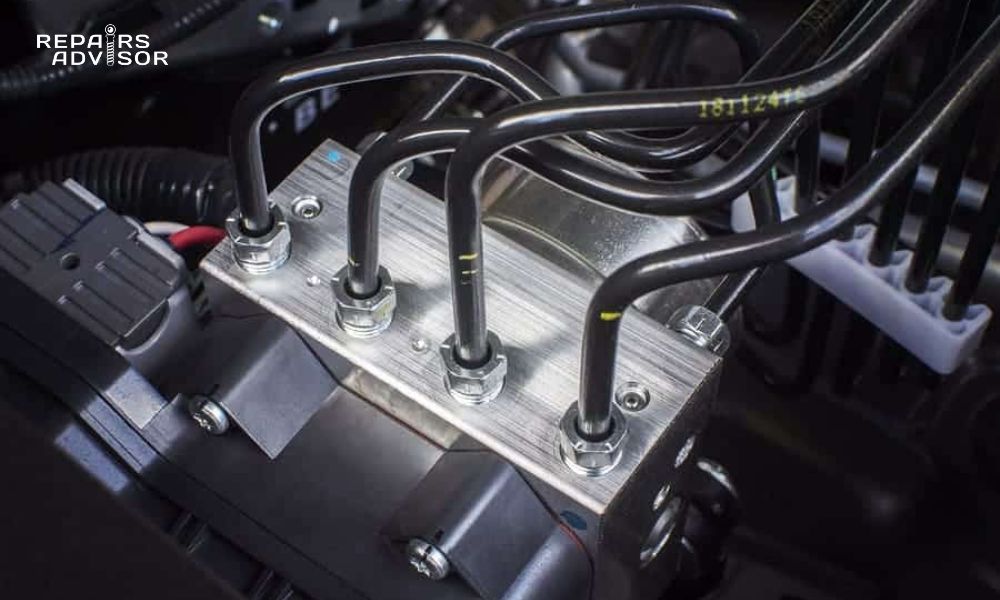
When you slam on your brakes in an emergency, there’s a sophisticated piece of machinery working behind the scenes to keep you safe. The ABS pump is the heart of your vehicle’s anti-lock braking system, providing the crucial hydraulic pressure needed to prevent wheel lockup and maintain steering control during emergency stops. This electric motor-driven component cycles brake pressure dozens of times per second, giving you that characteristic pulsating feel under your foot while keeping your wheels turning and your vehicle under control.
Understanding how your ABS pump works, recognizing the signs of failure, and knowing when to seek professional help can mean the difference between safe stops and dangerous skids. Whether you’re experiencing warning lights, unusual brake behavior, or strange noises during braking, this comprehensive guide provides the technical knowledge you need to diagnose problems and make informed repair decisions.
The ABS pump doesn’t work alone—it’s part of an integrated system that includes the ABS control module, wheel speed sensors, and hydraulic control valves. When any component fails, the entire Anti-lock Braking System can become compromised, potentially leaving you without this critical safety feature when you need it most.
Safety Notice: The information provided in this article is for reference only and should be implemented at your own risk and responsibility. ABS systems operate under high hydraulic pressure and involve critical safety components. Professional consultation is recommended for complex diagnostic procedures, and proper safety equipment is mandatory when performing any brake system work. Vehicle-specific procedures may vary significantly from the general information provided in this guide.
What is an ABS Pump and How Does It Work?
The ABS pump is a specialized electric motor-driven hydraulic pump that serves as the power source for your vehicle’s anti-lock braking system. This critical component generates and maintains the hydraulic pressure necessary to rapidly modulate brake force at individual wheels, preventing lockup while maintaining maximum braking effectiveness and steering control.
Definition and Primary Function
At its core, the ABS pump is responsible for creating the hydraulic pressure that enables the rapid cycling of brake force during ABS activation. When the ABS control module detects that a wheel is about to lock up, it commands the pump to generate additional pressure while simultaneously controlling hydraulic valves to modulate brake force. This process occurs many times per second, creating the characteristic pulsating sensation you feel in the brake pedal during emergency braking.
The pump operates on a simple yet effective principle: an electric DC motor drives a hydraulic pump that pressurizes brake fluid and stores it in an accumulator chamber. When ABS activation is required, this pressurized fluid is rapidly released and reapplied to individual brake circuits, allowing the system to prevent wheel lockup while maintaining braking force.
Integration with ABS System Components
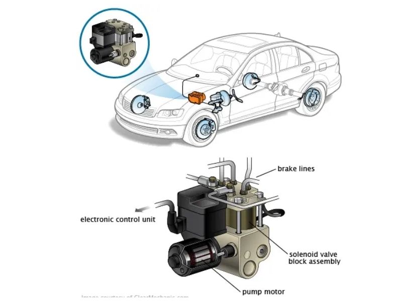
The ABS pump doesn’t operate in isolation—it’s intimately connected with other system components to create a cohesive safety system. The pump receives control signals from the ABS control module, which processes information from wheel speed sensors and determines when intervention is necessary. The hydraulic output from the pump feeds into the hydraulic control unit (HCU), which contains the solenoid valves that direct pressurized brake fluid to individual wheel circuits.
This integration means that pump failure affects not just basic ABS operation, but also related systems like traction control, electronic stability control, and hill-start assist. Modern vehicles rely on the ABS pump’s hydraulic pressure for multiple safety functions, making it a critical component for overall vehicle stability and control.
Types of ABS Pump Configurations
ABS pump designs vary significantly between manufacturers and vehicle applications. Integrated pump and module units combine the electric pump motor, hydraulic control unit, and electronic control module into a single assembly. This design saves space and weight but can make repairs more complex and expensive when failures occur.
Separate pump motor assemblies mount the electric motor separately from the hydraulic control unit, allowing for individual component replacement when problems arise. This configuration is common in trucks and commercial vehicles where serviceability is prioritized over packaging efficiency.
Manufacturer-specific designs reflect different engineering approaches to ABS implementation. Some systems use high-pressure accumulators to store energy, while others rely on rapid motor cycling. Understanding your specific system type is crucial for proper diagnosis and repair.
Operating Principles
The ABS pump operates through a sophisticated electromagnetic motor system that drives a positive displacement hydraulic pump. When the ignition is turned on, the system performs a brief self-test, and you may hear the pump motor run for a few seconds as it builds initial system pressure and verifies component operation.
During normal braking, the pump remains inactive, and brake force is transmitted directly from the master cylinder through the hydraulic control unit to the wheels. However, when wheel speed sensors detect impending lockup, the ABS control module immediately activates the pump motor while simultaneously operating solenoid valves to modulate brake pressure.
The pump rapidly generates hydraulic pressure, typically cycling at rates of 10-15 times per second during ABS activation. This rapid cycling creates the characteristic pulsating feel in the brake pedal and the distinctive noise associated with ABS operation. The system continues this rapid modulation until wheel speeds return to normal ranges or the driver reduces brake pedal pressure.
ABS Pump Components and System Integration
Understanding the individual components that make up the ABS pump assembly and how they integrate with the broader braking system is essential for effective diagnosis and repair. Modern ABS pumps are complex electro-hydraulic devices that combine precision electronic control with robust hydraulic components.
ABS Pump Motor Specifications
The heart of the ABS pump is a specialized DC electric motor designed to operate under demanding conditions. These motors typically operate on 12-volt vehicle electrical systems and are engineered to produce high torque output for brief periods during ABS activation. The motor construction features permanent magnet fields and wound armatures with carbon brush commutation systems.
Carbon brush technology is critical to pump motor operation. These brushes provide electrical contact between the stationary motor housing and the rotating armature. Over time, carbon brushes wear down through normal use, and eventual replacement becomes necessary. Brush wear is one of the most common causes of ABS pump failure, particularly in high-mileage vehicles.
Power supply requirements for ABS pump motors are substantial during operation. The motor may draw 20-40 amperes during active pumping cycles, requiring robust electrical connections and adequate charging system capacity. Poor electrical connections or weak charging systems can cause pump performance problems and premature component failure.
Amperage draw characteristics provide valuable diagnostic information. Normal pump motors should draw consistent current during operation, while failing motors may show excessive current draw, erratic patterns, or complete failure to draw current when commanded to operate.
Hydraulic Control Unit Interaction
The hydraulic control unit (HCU) works in close coordination with the pump motor to provide precise brake pressure control. The pump generates pressurized brake fluid that fills an accumulator chamber within the HCU. This pressurized fluid serves as the power source for rapid brake pressure modulation during ABS events.
Pump chamber design varies between manufacturers but typically features positive displacement pumps that move specific volumes of brake fluid with each motor revolution. Some systems use gear pumps, while others employ piston-type pumps. The choice affects system response characteristics and maintenance requirements.
Pressure accumulator function is crucial for system performance. The accumulator stores pressurized brake fluid generated by the pump, providing an immediate source of hydraulic energy when ABS activation is required. Accumulator failures can cause slow system response or complete ABS malfunction.
Solenoid valve coordination between the pump and HCU ensures proper pressure delivery to individual wheel circuits. The ABS control module coordinates pump operation with solenoid valve actuation to achieve precise pressure control at each wheel. Timing coordination between these components is critical for proper system operation.
ABS Module Control Integration
The electronic integration between the ABS pump and control module represents some of the most sophisticated automotive technology. The control module continuously monitors system status and controls pump operation through various electronic control strategies.
Electronic control signals from the ABS module to the pump motor include both on/off commands and variable control signals. Some systems use simple relay-controlled operation, while others employ more sophisticated pulse-width modulation (PWM) control for precise pump speed regulation.
PWM control systems allow the ABS module to vary pump motor speed based on system demands. This capability enables more precise pressure control and can reduce system noise during operation. However, PWM control systems are more complex and can be more challenging to diagnose when problems occur.
Feedback monitoring systems provide the ABS module with information about pump operation status. These may include pressure sensors, motor current monitoring, or position feedback systems that verify proper pump operation. Feedback system failures can cause the ABS module to disable the system even when the pump itself is functioning properly.
System Interconnections
The ABS pump connects to multiple vehicle systems, creating a web of interdependencies that affects both operation and diagnosis. Master cylinder connection provides the primary brake fluid supply to the pump and HCU assembly. Problems with master cylinder function or brake fluid supply can directly impact pump operation.
Individual wheel brake circuits receive modulated pressure from the pump through the HCU. Understanding circuit configurations—whether front/rear split, diagonal split, or individual wheel control—is essential for proper diagnosis and repair procedures.
Return line configuration allows brake fluid to return from the wheel circuits to the master cylinder reservoir during pressure release cycles. Blocked return lines can cause brake drag or system pressure buildup that affects pump operation.
Common Symptoms of ABS Pump Failure
Recognizing the symptoms of ABS pump failure early can prevent complete system breakdown and maintain your vehicle’s safety systems. ABS pump problems manifest in various ways, from obvious warning lights to subtle changes in brake system behavior that might be easy to overlook.
Primary Warning Indicators
ABS warning light activation is typically the first and most obvious sign of pump-related problems. This amber or red warning light on your dashboard indicates that the ABS system has detected a fault and may have disabled anti-lock functionality to prevent unpredictable system behavior. When this light appears, the system has likely detected either pump motor failure, pressure sensor problems, or communication issues with the pump assembly.
Traction control light illumination often accompanies ABS pump problems because modern traction control systems rely on the same hydraulic pump for operation. When the pump fails, both ABS and traction control systems become unavailable, triggering multiple warning lights simultaneously.
Electronic stability control warnings appear on vehicles equipped with ESC systems when the ABS pump fails. These advanced stability systems depend on rapid brake pressure modulation provided by the ABS pump, so pump failure disables these critical safety features.
Check engine light activation can occur in some vehicles when ABS pump problems affect other vehicle systems. This is particularly common in vehicles where the ABS system provides speed information for transmission control or other engine management functions.
Performance-Related Symptoms
Hard brake pedal feel is one of the most noticeable performance symptoms of ABS pump failure. When the pump cannot generate adequate hydraulic pressure, the brake pedal requires significantly more effort to achieve the same braking force. This symptom often develops gradually as pump performance degrades, making it easy to overlook until the problem becomes severe.
Increased brake pedal effort required during normal braking situations indicates that the pump is not providing adequate assistance to the braking system. You may find yourself pushing much harder on the brake pedal to achieve stops that were previously accomplished with light pedal pressure.
Loss of anti-lock braking function becomes apparent during emergency braking situations. Without a functioning pump, wheels may lock up during hard braking, particularly on wet or slippery surfaces. This loss of function significantly increases the risk of losing vehicle control during emergency stops.
Brake pedal pulsation irregularities can occur when pump problems affect the hydraulic control unit’s ability to modulate brake pressure properly. Instead of the normal, rhythmic pulsation during ABS activation, you might experience erratic or absent pulsation patterns.
Audible Symptoms
Continuous pump motor operation is a clear indication of system problems. If you hear the ABS pump motor running constantly after starting the vehicle or during normal driving, this typically indicates that the system is unable to build or maintain proper pressure, often due to internal pump wear or hydraulic leakage.
Grinding or clicking noises during braking can indicate mechanical problems within the pump assembly. These sounds might originate from worn motor bearings, damaged pump components, or debris within the hydraulic system. Any unusual noises during braking should be investigated immediately.
Unusual hydraulic noises such as whining, squealing, or chattering sounds during ABS activation can indicate pump motor problems or hydraulic system issues. Normal ABS operation produces distinct sounds, but any new or different noises warrant immediate attention.
Pump cycling without braking input occurs when the system attempts to maintain pressure due to internal leakage or pressure sensor malfunctions. This symptom often accompanies continuous motor operation and indicates serious system problems.
System Behavior Changes
Brake fluid pressure loss manifests as a gradually sinking brake pedal or the need to pump the brakes to achieve adequate stopping power. This symptom can indicate internal pump leakage or hydraulic control unit problems that prevent proper pressure maintenance.
Uneven braking performance between individual wheels can occur when pump problems affect the hydraulic control unit’s ability to provide equal pressure to all brake circuits. This might cause the vehicle to pull to one side during braking or result in inconsistent stopping distances.
Vehicle pulling during braking can result from uneven brake pressure distribution caused by pump or hydraulic control unit malfunctions. This symptom is particularly dangerous as it can cause loss of directional control during braking.
Speedometer malfunction occurs in rare cases where ABS pump problems affect vehicle speed sensor circuits or communication systems. Some vehicles rely on ABS system data for speedometer operation, so pump failures can occasionally cause speedometer irregularities.
Advanced System Effects
Modern vehicles integrate ABS pumps with multiple advanced safety systems, so pump failure often has widespread effects beyond basic brake operation. Traction control system failure leaves you without assistance during acceleration on slippery surfaces, increasing the risk of wheel spin and loss of control.
Electronic stability control loss is particularly concerning because ESC systems help prevent rollovers and maintain vehicle stability during emergency maneuvers. Without a functioning ABS pump, these critical safety interventions become unavailable.
Hill-start assist deactivation affects vehicles equipped with this feature, making it more difficult to start smoothly on inclines without rollback. While not immediately dangerous, this loss of assistance can be particularly challenging for inexperienced drivers.
Brake assist system malfunction disables emergency brake assist features that can automatically increase brake force during panic stops. This loss of assistance can result in longer stopping distances during emergency situations.
Causes of ABS Pump Failure
Understanding why ABS pumps fail helps you make informed decisions about repairs and take preventive measures to extend system life. ABS pump failures typically result from a combination of factors including electrical problems, mechanical wear, environmental damage, and system-related issues.
Electrical Failure Modes
Carbon brush wear and degradation represents the most common cause of ABS pump motor failure. Carbon brushes provide electrical contact between the stationary motor housing and rotating armature, but they gradually wear away through normal use. High-mileage vehicles are particularly susceptible to brush wear, which initially causes intermittent operation before progressing to complete motor failure.
Motor winding failures occur when the copper wire windings in the motor armature or field coils break down due to heat, vibration, or electrical stress. These failures often result from excessive current draw caused by mechanical binding, overheating, or voltage spikes in the electrical system. Winding failures typically require complete motor replacement rather than repair.
Connector corrosion and looseness frequently cause intermittent pump operation or complete failure. The high current demands of ABS pump motors make them particularly sensitive to poor electrical connections. Corrosion on connector pins creates high resistance that can cause voltage drops, overheating, and eventual component failure.
Power supply circuit problems including damaged wiring, blown fuses, or failing relays can prevent the pump from receiving adequate power. These issues are often easier and less expensive to repair than actual pump problems, making proper diagnosis crucial before replacing expensive components.
Mechanical Wear Factors
Pump chamber wear occurs gradually as the internal components of the hydraulic pump experience normal wear from pressurizing brake fluid thousands of times over the vehicle’s lifetime. Wear in pump chambers reduces the unit’s ability to generate adequate pressure, leading to poor ABS performance and eventual system failure.
Seal deterioration and leakage within the pump assembly can cause internal hydraulic leakage that prevents proper pressure buildup. Brake fluid is hygroscopic, meaning it absorbs moisture from the air, and this moisture can cause seal swelling, cracking, and eventual failure. Regular brake fluid changes help prevent seal deterioration.
Motor bearing failure results from the high loads and rapid cycling that ABS pump motors experience during operation. Bearings support the rotating armature and must withstand both radial and axial loads during pump operation. Bearing failure typically produces grinding noises and can lead to armature damage if not addressed promptly.
Rotor magnetization loss can occur in permanent magnet motors over time, particularly when exposed to excessive heat or electrical stress. Loss of magnetic strength reduces motor torque output and can cause the pump to operate sluggishly or fail to generate adequate pressure.
Environmental Damage
Moisture intrusion and corrosion pose significant threats to ABS pump longevity, particularly in harsh climates. Water can enter pump assemblies through damaged seals or connectors, causing internal corrosion that affects both electrical and mechanical components. Once moisture enters the system, it accelerates deterioration of multiple components simultaneously.
Road salt and chemical exposure create highly corrosive conditions that attack both the external pump housing and internal components. De-icing chemicals used on winter roads are particularly aggressive, and their effects are compounded by the repeated heating and cooling cycles that occur during normal vehicle operation.
Temperature extremes impact pump operation and longevity in multiple ways. Extreme cold can cause seals to harden and crack, while excessive heat can break down electrical insulation and cause hydraulic seals to deteriorate. ABS pumps must operate reliably across temperature ranges from well below freezing to over 200°F (93°C) in some under-hood installations.
Contamination from brake fluid breakdown occurs when brake fluid exceeds its service life and begins to deteriorate chemically. Old brake fluid can become acidic and contain particles that damage pump internal components. This contamination can cause accelerated wear and eventual pump failure.
System-Related Causes
Brake fluid contamination from various sources can cause pump problems even when the fluid appears clean. Contamination can come from incorrect fluid types, mixing different fluid formulations, or infiltration of petroleum products that cause seal swelling and system damage.
Air in hydraulic system forces the pump to work harder to generate adequate pressure and can cause erratic system operation. Air enters the system through leaks, improper bleeding procedures, or component failures that allow atmospheric air to infiltrate the closed hydraulic system.
Excessive system cycling can occur when other ABS components malfunction and cause the pump to operate more frequently than normal. For example, faulty wheel speed sensors might cause unnecessary ABS activation, leading to premature pump wear from excessive cycling.
Inadequate maintenance intervals contribute to pump failure when brake fluid is not changed according to manufacturer recommendations. Old brake fluid contains moisture and contaminants that accelerate component deterioration and can cause premature pump failure.
Understanding these failure modes helps you make informed decisions about repairs and maintenance. Many pump failures can be prevented through proper maintenance, while others are simply the result of normal wear and require replacement when they occur. The key is accurate diagnosis to determine whether you’re dealing with a preventable problem or normal component wear that requires replacement.
Professional Diagnostic Procedures
Accurate diagnosis of ABS pump problems requires a systematic approach that combines visual inspection, electronic testing, and hydraulic system evaluation. Professional-grade diagnostic procedures help distinguish between actual pump failures and other system problems that might produce similar symptoms.
Initial System Evaluation
Visual inspection of pump assembly should be the first step in any diagnostic procedure. Examine the pump housing for obvious signs of damage, leakage, or corrosion. Look for brake fluid stains around the pump assembly, which can indicate internal or external leakage. Check that all mounting bolts are secure and that the pump is properly positioned in its mounting bracket.
Checking electrical connections involves inspecting all connectors, wiring harnesses, and fuses related to the ABS pump circuit. Look for corrosion, loose connections, damaged wiring, or signs of overheating. Pay particular attention to the main pump motor connector, which carries high current and is susceptible to heat damage and corrosion.
Brake fluid level and condition assessment provides important diagnostic information. Low brake fluid levels can cause pump problems, while contaminated or old brake fluid can indicate system-wide issues that might affect pump operation. Dark, dirty, or contaminated brake fluid often indicates inadequate maintenance that could contribute to pump failure.
Warning light pattern analysis can provide valuable diagnostic clues. Note which warning lights are illuminated and when they appear. Some systems display specific warning light patterns that indicate different types of problems. Document whether lights appear continuously, intermittently, or only under specific driving conditions.
OBD-II Diagnostic Scanning
ABS-specific fault code retrieval requires a scan tool capable of accessing ABS system data. Generic OBD-II scanners may not provide sufficient detail for ABS diagnosis, so professional-grade scan tools are often necessary. Retrieve all stored and pending codes before beginning other diagnostic procedures, as codes provide important clues about system problems.
Live data parameter monitoring allows you to observe pump operation in real-time. Monitor parameters such as pump motor current draw, system pressure readings, individual wheel speeds, and module commands to the pump. Compare observed values with manufacturer specifications to identify abnormal operation.
Freeze frame data analysis shows vehicle operating conditions when fault codes were set. This information helps determine whether problems occur under specific circumstances such as cold starts, highway driving, or hard braking conditions. Freeze frame data can help identify intermittent problems that might not be apparent during static testing.
Manufacturer-specific code interpretation is crucial because different manufacturers use different code definitions and diagnostic procedures. Consult appropriate service information for your specific vehicle to ensure accurate code interpretation and proper diagnostic procedures.
Electrical Testing Procedures
Power supply voltage verification ensures the pump motor receives adequate voltage during operation. Use a digital multimeter to measure voltage at the pump connector while commanding pump operation with a scan tool. Voltage should remain within manufacturer specifications under load conditions.
Ground circuit resistance testing is equally important because ABS pump motors draw high current and require excellent ground connections. Measure voltage drop across ground circuits while the pump is operating. Excessive voltage drop indicates high resistance that can cause pump performance problems.
Motor current draw measurement provides excellent diagnostic information about pump motor condition. Use an amp clamp or current probe to measure pump motor amperage during operation. Compare measured values with specifications—excessive current draw often indicates mechanical problems, while low current draw might indicate electrical problems.
Control signal verification involves checking the signals from the ABS control module to the pump motor. Use an oscilloscope or scan tool to verify that the module is sending proper control signals to the pump. Missing or incorrect control signals indicate module problems rather than pump failures.
Hydraulic System Testing
Pump pressure output measurement requires specialized pressure testing equipment designed for ABS systems. Connect pressure gauges to appropriate test ports and measure pump output pressure during operation. Compare measured pressures with manufacturer specifications to determine if the pump can generate adequate pressure.
System leak testing procedures help identify internal or external leakage that might affect pump performance. Some leakage tests involve pressurizing the system and monitoring pressure decay over time. Internal leakage within the pump or hydraulic control unit can prevent proper pressure buildup even when the pump motor operates normally.
Flow rate verification measures the volume of brake fluid the pump can move over a specific time period. Low flow rates can indicate pump wear or internal restrictions that affect system performance. Flow testing typically requires specialized equipment and should be performed according to manufacturer procedures.
Accumulator pressure testing verifies that pressure storage components function properly. Some ABS systems use accumulators to store pressurized brake fluid for immediate availability during ABS activation. Accumulator failures can cause slow system response or inadequate pressure during operation.
Advanced Diagnostic Techniques
Oscilloscope signal analysis provides detailed information about pump motor operation that simple voltage measurements cannot reveal. Oscilloscope patterns can show motor commutation quality, electrical noise, and timing relationships that help identify specific problem areas within the pump assembly.
Pump motor activation testing using scan tool commands allows you to operate the pump motor independently of normal ABS operation. This testing helps determine whether pump problems are internal to the pump assembly or related to control module operation.
Individual circuit isolation involves systematically disconnecting and testing individual components to isolate the source of problems. This approach is particularly useful when multiple fault codes are present or when problems appear to involve multiple system components.
Component substitution testing can help confirm diagnoses when the exact cause of problems remains unclear. Temporarily substituting known-good components can help verify diagnoses before committing to expensive repairs.
Professional Scan Tool Functions
Modern scan tools provide sophisticated ABS testing capabilities that greatly enhance diagnostic accuracy. ABS pump activation commands allow technicians to operate the pump motor on demand, enabling testing under controlled conditions. This capability is essential for verifying pump operation and measuring performance parameters.
Individual valve testing functions enable testing of solenoid valves within the hydraulic control unit. These tests help determine whether problems originate in the pump assembly or in the hydraulic control components that direct pressurized fluid to individual wheels.
System bleeding procedures available through scan tools ensure proper system operation after repairs. Many ABS systems require specific bleeding procedures that can only be performed with appropriate scan tool functions. Failure to perform proper bleeding can result in poor system performance even after successful repairs.
ABS Pump Repair vs. Replacement Decision
When faced with ABS pump problems, choosing between repair and replacement requires careful consideration of multiple factors including cost, reliability, time investment, and long-term value. Understanding when repair is viable and when replacement is necessary can save both money and future headaches.
Repair Feasibility Assessment
Carbon brush replacement procedures represent one of the most common and cost-effective ABS pump repairs. Carbon brushes are wear items that eventually require replacement in all electric motors, and ABS pump motors are no exception. If brush replacement is the only issue, repair costs typically range from $150-300 compared to $500-1200 for pump replacement.
However, carbon brush replacement requires disassembly of the pump motor, which may void warranties and requires specialized knowledge. The repair is only viable if the motor commutator (the segmented copper contact surface) is in good condition. Damaged or severely worn commutators require complete motor replacement.
Connector cleaning and repair can resolve many electrical problems at minimal cost. Corroded or loose electrical connections are common causes of pump problems, particularly in vehicles exposed to harsh environments. Professional connector cleaning and sealing can often restore proper operation for under $100.
Seal replacement options exist for some pump designs, but accessibility varies significantly between manufacturers. External seal replacement might be feasible, but internal seal replacement often requires complete pump disassembly that approaches the cost of replacement units.
Motor rebuilding considerations involve replacing multiple internal components including brushes, bearings, and sometimes armature assemblies. Motor rebuilding requires specialized equipment and expertise, making it economically viable only for expensive pump assemblies or when replacement parts are unavailable.
When Repair is Viable
Minor electrical connection issues often respond well to cleaning and repair procedures. If diagnostic testing shows that the pump motor operates properly when supplied with clean power and ground connections, connector repair might resolve the problem completely.
Carbon brush wear only presents an excellent repair opportunity if other motor components are in good condition. Professional motor shops can often replace brushes and recondition commutators for significantly less than replacement costs.
External seal leakage might be repairable if seals are accessible and replacement parts are available. However, external leakage often indicates more extensive internal problems that make replacement more cost-effective.
Contamination-related problems sometimes respond to thorough cleaning and fresh brake fluid. If contamination hasn’t caused permanent component damage, cleaning and proper maintenance might restore operation without major component replacement.
When Replacement is Necessary
Motor winding failures typically require complete motor replacement because rewinding automotive motors is rarely cost-effective. Winding failures usually result from overheating, electrical spikes, or mechanical damage that affects multiple motor components.
Hydraulic chamber damage within the pump assembly often requires complete unit replacement. Hydraulic chambers operate under high pressure and tight tolerances, making repair difficult or impossible without specialized equipment.
Electronic control circuit failure in integrated pump and module assemblies typically necessitates complete unit replacement. The electronic components integrated into modern ABS pumps are complex and difficult to repair independently.
Multiple component failures make repair economically unfeasible. When several pump components fail simultaneously, replacement becomes more cost-effective than attempting multiple repairs with uncertain outcomes.
Cost-Benefit Analysis
Repair vs. replacement costs vary significantly based on vehicle type, pump design, and available parts. Basic pump motor repairs might cost $200-400, while complete replacements range from $500-1500 depending on the vehicle and whether you choose OEM, remanufactured, or aftermarket units.
Labor time considerations affect the total cost equation. Pump repairs often require more labor time than replacement because of the additional disassembly, testing, and reassembly required. Factor in diagnostic time, repair procedures, and system bleeding when comparing total costs.
Warranty implications strongly favor replacement over repair in many cases. New and remanufactured pumps typically include warranties ranging from one year to unlimited mileage, while repairs often carry limited or no warranty coverage.
Long-term reliability factors must be considered when making repair decisions. A repaired pump might function adequately but have shorter service life than a replacement unit. Consider the vehicle’s age, mileage, and your planned ownership duration when making decisions.
Professional vs. DIY Considerations
Specialized tool requirements for ABS pump service include high-pressure test equipment, specialized scan tools, and brake bleeding equipment. These tools represent significant investments that make professional service more cost-effective for most individuals.
Technical expertise needs for ABS pump service extend beyond basic mechanical skills. Proper diagnosis requires understanding of hydraulic systems, electrical circuits, and vehicle-specific procedures. Mistakes can result in brake system failure with potentially catastrophic consequences.
Safety risk assessment must consider that brake systems are critical safety components. Improper repairs can result in brake failure, loss of vehicle control, and serious accidents. Professional service provides expertise, proper equipment, and warranty protection that DIY repairs cannot match.
Warranty preservation considerations apply to vehicles still under manufacturer or extended warranty coverage. Unauthorized repairs might void warranty coverage, making professional service the only viable option for some vehicles.
For most vehicle owners, ABS pump replacement by qualified professionals represents the best balance of cost, reliability, and safety. While repairs might seem attractive from a cost perspective, the complexity of modern ABS systems and the critical nature of brake system operation generally favor replacement with properly warranted components installed by experienced technicians.
Step-by-Step Replacement Guide
ABS pump replacement is a complex procedure that requires specialized knowledge, proper equipment, and strict attention to safety protocols. This guide provides comprehensive information for understanding the replacement process, though professional service is recommended for most situations due to the critical nature of brake system components.
Pre-Replacement Preparation
Required tools and equipment for ABS pump replacement extend beyond basic automotive tools. You’ll need a complete metric and standard socket set, wrenches, screwdrivers, and specialized brake tools including line wrenches for hydraulic connections. Additionally, you’ll require a scan tool capable of ABS system bleeding, pressure bleeding equipment, and possibly a lift or secure jack stands for vehicle access.
Safety equipment and precautions are absolutely critical when working on brake systems. Use safety glasses to protect against brake fluid splashes, nitrile gloves to prevent skin contact with brake fluid, and ensure adequate ventilation when working with brake fluids. Never smoke or allow open flames near brake fluid, as it is flammable and toxic.
Parts identification and procurement requires careful attention to vehicle-specific requirements. ABS pumps are often unique to specific vehicle models, engine types, and option packages. Verify part numbers using your vehicle identification number (VIN) and consider whether you want OEM, remanufactured, or aftermarket replacement units. Each option offers different cost and warranty characteristics.
Vehicle preparation procedures include parking on level ground, engaging the parking brake (if it operates independently of the ABS system), and ensuring the engine is cool before beginning work. Clean the work area around the ABS pump to prevent contamination of the hydraulic system during the repair process.
System Depressurization
Brake fluid reservoir management begins with removing brake fluid from the master cylinder reservoir to prevent overflow during pump removal. Use a turkey baster or brake fluid suction gun to reduce fluid levels, but don’t completely empty the reservoir as this can introduce air into the system.
Hydraulic pressure relief procedures are essential because ABS systems maintain residual pressure even when the vehicle is off. Many systems include pressure relief procedures in the scan tool functions, while others require specific pedal pumping sequences to relieve stored pressure. Consult vehicle-specific service information for proper procedures.
Line disconnection safety requires careful attention to brake fluid handling. Brake fluid is corrosive to paint and harmful to skin, so take appropriate precautions. Have clean rags ready to catch fluid spills and immediately clean any fluid that contacts painted surfaces.
Contamination prevention measures include keeping brake fluid containers sealed, using only clean tools and equipment, and preventing dirt or debris from entering opened hydraulic connections. Contamination during repair can cause expensive damage to the entire brake system.
Removal Procedure
Electrical connector disconnection should be performed with the ignition off and battery disconnected to prevent accidental system activation. Remove the main pump motor connector carefully, noting the orientation for proper reassembly. Some systems have multiple electrical connections that must be documented before removal.
Hydraulic line removal sequence is critical for maintaining system organization and preventing confusion during reassembly. Mark or photograph line positions before removal, and remove lines in the sequence specified by the manufacturer. Some lines may be under residual pressure despite depressurization procedures.
Mounting bolt removal requires attention to bolt access and torque requirements. ABS pumps are typically secured with several bolts that may require different socket sizes. Some bolts may be in difficult-to-access locations that require special tools or creative approaches.
Pump assembly extraction must be done carefully to avoid damage to surrounding components or brake lines. Some pump assemblies are heavy and awkwardly shaped, requiring two people for safe removal. Protect brake line connections and electrical connectors during removal.
Installation of Replacement Pump
New pump preparation includes verifying part number accuracy and inspecting the new unit for shipping damage. Some replacement pumps require initial setup procedures or pre-installation checks specified by the manufacturer. Remove all protective coverings and plugs from hydraulic connections just before installation.
Mounting and alignment procedures must follow manufacturer specifications exactly. Improper mounting can cause vibration, noise, or premature component failure. Ensure all mounting surfaces are clean and that the pump assembly seats properly in its mounting bracket before tightening bolts to specified torque values.
Torque specifications for connections are critical for both mechanical and hydraulic connections. Over-tightening can damage components or strip threads, while under-tightening can cause leaks or component looseness. Use a calibrated torque wrench and follow manufacturer specifications exactly.
Hydraulic line reconnection requires careful attention to thread engagement and sealing. Start all fittings by hand to prevent cross-threading, then tighten to specification using proper line wrenches. Some connections may require new sealing washers or O-rings that should be included with the replacement pump.
System Initialization Procedures
Brake fluid filling and bleeding represents one of the most critical aspects of ABS pump replacement. ABS systems require specific bleeding procedures that differ significantly from conventional brake bleeding. The system must be completely free of air for proper operation, and trapped air in the pump or hydraulic control unit can cause system malfunction.
ABS system bleeding requirements typically involve using a scan tool to activate the pump and cycle solenoid valves while performing bleeding procedures. This process ensures that air is purged from all internal passages and chambers. Standard bleeding procedures are insufficient for ABS systems and can leave air trapped in the system.
Electronic module programming may be required when replacing integrated pump and module assemblies. Some systems require initialization procedures to teach the new module about vehicle-specific parameters such as wheel circumferences, gear ratios, and system calibrations. This programming typically requires dealer-level scan tools and procedures.
System function verification involves testing all aspects of ABS operation to ensure proper system function. This includes verifying that warning lights operate correctly, the pump responds to scan tool commands, and system pressure meets specifications.
Post-Installation Testing
Diagnostic code clearing removes any fault codes stored during the replacement procedure. However, don’t clear codes until you’ve verified that the replacement has resolved the original problems. Some codes may reappear if underlying problems haven’t been fully addressed.
System pressure testing verifies that the new pump can generate adequate pressure and that the hydraulic system holds pressure properly. Use appropriate pressure testing equipment and compare results to manufacturer specifications.
Road test procedures should begin with low-speed testing in a safe area before progressing to normal driving conditions. Test brake pedal feel, ABS operation (if safe to do so), and verify that all warning lights remain off during normal operation.
Final system verification includes confirming that all safety systems function properly, including ABS, traction control, and electronic stability control where equipped. Document all test results and ensure the customer understands proper system operation.
ABS System Bleeding and Programming
Proper system bleeding and programming procedures are essential for reliable ABS operation after pump replacement. These procedures differ significantly from conventional brake bleeding and often require specialized equipment and knowledge.
Conventional Bleeding Limitations
Why standard bleeding isn’t sufficient relates to the complex internal passages within ABS systems. Traditional brake bleeding relies on gravity or manual pressure to move fluid through the system, but ABS pumps and hydraulic control units contain chambers and passages that can trap air even after conventional bleeding procedures.
Trapped air in pump chambers can cause poor system performance, spongy brake pedal feel, and premature component failure. Air compresses under pressure, preventing the system from generating adequate hydraulic force and causing erratic operation during ABS activation.
Solenoid valve position requirements mean that certain internal passages are only accessible when solenoid valves are in specific positions. Without scan tool control of valve positions, conventional bleeding cannot access all system passages.
System priming needs require that the pump and hydraulic control unit be completely filled with brake fluid before normal operation. This priming process typically requires scan tool activation of the pump while performing bleeding procedures.
Professional Bleeding Procedures
Scan tool bleeding functions are essential for proper ABS system bleeding. These functions allow technicians to control pump operation and solenoid valve positions while performing bleeding procedures. Different manufacturers use different bleeding sequences, so vehicle-specific procedures must be followed exactly.
Pump activation sequences typically involve the scan tool commanding the pump to run while bleeding procedures are performed at individual wheels. This process helps move trapped air through the system and ensures complete fluid circulation through all passages.
Individual valve cycling allows each solenoid valve to be operated independently, ensuring that all internal passages are accessible during bleeding procedures. This cycling process must be coordinated with bleeding at individual wheels to achieve complete air removal.
Pressure bleeding techniques using specialized pressure bleeding equipment can enhance bleeding effectiveness when combined with scan tool functions. Pressure bleeding provides consistent fluid pressure throughout the procedure and can help push trapped air through complex internal passages.
Programming and Coding Requirements
Module initialization procedures are often required when replacing integrated ABS pump and module assemblies. These procedures teach the new module about vehicle-specific parameters and ensure proper communication with other vehicle systems.
Vehicle-specific programming needs vary significantly between manufacturers and even between different models from the same manufacturer. Some systems require extensive programming that can only be performed with dealer-level equipment, while others require minimal or no programming.
Dealer-level tool requirements for programming reflect the complexity of modern ABS systems and their integration with other vehicle systems. Independent repair facilities may need to subcontract programming procedures to dealerships or invest in expensive professional-grade equipment.
Communication protocol setup ensures that the ABS system can communicate properly with other vehicle systems such as engine management, transmission control, and body control modules. Improper communication setup can cause system malfunctions or prevent proper operation of related systems.
System Verification Methods
Functionality testing procedures should include verification of all ABS system functions including pump operation, solenoid valve function, and proper system pressure generation. Use scan tool live data functions to monitor system operation during testing.
Warning light confirmation involves verifying that all warning lights operate correctly and that no unwanted lights remain illuminated after successful repair. Some systems perform self-tests that must complete successfully before normal operation begins.
Performance validation includes road testing under controlled conditions to verify proper system operation. Test brake pedal feel, ABS activation (where safe), and integration with other vehicle systems.
Long-term monitoring may be necessary to ensure continued proper operation. Some intermittent problems may not be apparent immediately after repair, so follow-up inspections may be necessary to confirm successful repair.
Maintenance and Prevention Strategies
Proactive maintenance and prevention strategies can significantly extend ABS pump life and prevent expensive failures. Understanding what causes pump problems and taking steps to prevent them is far more cost-effective than dealing with failures after they occur.
Regular Inspection Schedule
Visual checks during routine service should include examination of the ABS pump assembly, electrical connections, and surrounding components. Look for signs of leakage, corrosion, or physical damage that might indicate developing problems. Pay attention to brake fluid stains or residue that might indicate system leakage.
Brake fluid quality monitoring is crucial for ABS system longevity. Brake fluid is hygroscopic, meaning it absorbs moisture from the air over time. This moisture causes corrosion within the system and can lead to premature component failure. Check brake fluid color and consistency during routine service intervals.
System warning light attention means addressing ABS warning lights promptly rather than ignoring them. Early intervention often prevents minor problems from becoming major failures. Warning lights indicate that the system has detected problems that require attention.
Professional system evaluation should be performed annually or according to manufacturer recommendations. Professional technicians have the diagnostic equipment and expertise necessary to identify developing problems before they cause system failures.
Brake Fluid Maintenance
Replacement interval importance cannot be overstated for ABS system longevity. Most manufacturers recommend brake fluid replacement every 2-3 years regardless of mileage, but harsh driving conditions may require more frequent replacement. Construction and equipment vehicles operating in severe conditions often require annual brake fluid replacement.
Contamination prevention involves using only the specified brake fluid type and avoiding contamination during service procedures. Never reuse brake fluid, and ensure that new fluid comes from sealed containers. Different brake fluid types are not compatible and can cause system damage if mixed.
Moisture content monitoring can be performed using simple test strips that indicate brake fluid moisture content. Brake fluid with high moisture content should be replaced immediately to prevent system corrosion and component failure.
Quality specification compliance means using only brake fluid that meets or exceeds manufacturer specifications. Generic or substandard brake fluids may not provide adequate protection for sophisticated ABS components and can cause premature failures.
Environmental Protection Measures
Connector protection and sealing helps prevent electrical problems that commonly affect ABS pumps. Apply dielectric grease to electrical connections during service and ensure that connector seals are in good condition. Replace damaged connector seals to prevent moisture intrusion.
Corrosion prevention strategies are particularly important for vehicles operated in harsh environments. Regular undercarriage washing helps remove road salt and chemicals that cause corrosion. Consider applying corrosion protection treatments to ABS components in severe service applications.
Temperature extreme considerations involve protecting the ABS pump from excessive heat and cold. Ensure that heat shields are properly installed and that the pump has adequate ventilation. Cold weather operation may require longer warm-up periods to ensure proper system function.
Road salt exposure mitigation includes regular washing during winter months and prompt attention to any signs of corrosion around ABS components. Road salt is particularly aggressive and can cause rapid deterioration of both electrical and mechanical components.
Driving Habits for System Longevity
Avoiding unnecessary ABS activation helps reduce system wear and extends component life. While ABS systems are designed to handle emergency situations, unnecessary activation increases wear on all system components including the pump.
Smooth braking practices reduce stress on the entire brake system and minimize the need for ABS intervention. Gradual, progressive braking is easier on all brake system components and reduces the likelihood of wheel lockup situations that require ABS activation.
System testing in safe conditions allows you to verify proper ABS operation without creating dangerous situations. Occasional testing in controlled environments helps ensure that the system will function properly when needed in emergencies.
Prompt attention to warning signs means addressing any unusual brake system behavior immediately rather than waiting for complete system failure. Early intervention often prevents minor problems from becoming major repairs.
Cost Analysis and Professional Service
Understanding the costs associated with ABS pump service helps you make informed decisions about repair approaches and budget planning. Consider both immediate costs and long-term value when evaluating repair options.
Replacement Cost Breakdown
OEM vs. aftermarket pump pricing varies significantly based on vehicle type and manufacturer. Original Equipment Manufacturer (OEM) pumps typically cost $400-800 for most applications, while quality aftermarket units range from $250-600. Premium European vehicles may have significantly higher costs, with some units exceeding $1200.
Remanufactured unit options provide a middle ground between new and aftermarket pricing, typically costing $200-500 depending on the application. Quality remanufactured units undergo extensive rebuilding processes and often include warranties comparable to new units.
Labor cost estimates for ABS pump replacement typically range from 3-5 hours depending on vehicle accessibility and system complexity. Shop labor rates vary from $100-150 per hour in most markets, with dealership rates often higher than independent shops.
Additional parts and fluids can add $50-150 to the total repair cost. These costs include brake fluid, new sealing washers or O-rings, and potentially new brake hoses if the old ones are damaged during removal. Factor these costs into your repair budget planning.
Professional Service Advantages
Specialized diagnostic equipment available at professional shops enables accurate diagnosis that can save money by avoiding unnecessary part replacement. Professional scan tools provide capabilities that generic code readers cannot match, ensuring accurate problem identification.
Programming and coding capabilities are essential for many modern ABS systems and typically require dealer-level equipment. Independent shops may need to subcontract programming procedures, but they often have established relationships that streamline the process.
Warranty coverage provisions from professional installations typically include both parts and labor warranties that provide protection against defective components or installation errors. These warranties can save significant money if problems occur after repair.
System integration expertise ensures that replacement pumps work properly with other vehicle systems. Professional technicians understand the complex interactions between ABS systems and other vehicle components, preventing problems that might not be apparent to DIY repairs.
DIY Feasibility Assessment
Required skill level evaluation for ABS pump replacement includes mechanical aptitude, electrical troubleshooting ability, and understanding of hydraulic systems. The repair requires intermediate to advanced skills and comfort working with critical safety systems.
Tool investment considerations include the cost of specialized scan tools, pressure bleeding equipment, and other professional-grade tools required for proper repair. These tools may cost more than professional repair for single-use applications.
Risk vs. benefit analysis must consider that brake systems are critical safety components where mistakes can have serious consequences. Professional repair provides expertise, proper equipment, and warranty protection that DIY repairs cannot match.
Time commitment requirements for DIY repairs often exceed initial estimates, particularly when complications arise. Factor in diagnostic time, parts procurement delays, and potential need for professional assistance if problems occur.
Long-Term Value Considerations
Reliability expectations vary between repair approaches and component choices. Professional installation of quality components typically provides the best long-term reliability, while cost-cutting approaches may result in shorter service life.
Warranty comparisons between different repair approaches and component choices affect long-term value. Consider both warranty length and what is covered when making repair decisions.
Performance characteristics of replacement components affect vehicle operation and safety. Quality components typically provide performance characteristics closer to original equipment specifications.
Service life projections help evaluate the total cost of ownership for different repair approaches. A more expensive repair that lasts longer may provide better value than a cheaper repair that requires repeated service.
For most vehicle owners, professional ABS pump replacement represents the best balance of cost, reliability, and safety. The complexity of modern ABS systems, the critical nature of brake system operation, and the specialized equipment required for proper service generally favor professional repair over DIY approaches.
Related ABS System Components
Understanding how ABS pumps interact with other system components helps you recognize potential problems and make informed repair decisions. The ABS system functions as an integrated unit where component failures can affect multiple system functions.
ABS Control Module Function
The ABS control module serves as the brain of the entire system, processing sensor inputs and controlling pump operation. This sophisticated computer continuously monitors wheel speeds, vehicle acceleration, brake pedal position, and other parameters to determine when ABS intervention is necessary.
When the control module detects impending wheel lockup, it immediately commands the ABS pump to generate hydraulic pressure while simultaneously controlling solenoid valves to modulate brake pressure at individual wheels. The module’s ability to process information and respond within milliseconds is crucial for effective ABS operation.
Control module failures can mimic pump problems because the module controls pump operation. Proper diagnosis must distinguish between actual pump failures and control module problems that prevent the pump from receiving proper control signals.
Hydraulic Control Unit Operation
The hydraulic control unit (HCU) works in close coordination with the ABS pump to provide precise brake pressure control. The HCU contains solenoid valves, accumulators, and fluid passages that direct pressurized brake fluid from the pump to individual wheel circuits.
During ABS activation, the pump generates hydraulic pressure that the HCU uses to rapidly modulate brake pressure at individual wheels. This coordination between pump and HCU creates the characteristic pulsating sensation in the brake pedal during ABS operation.
HCU problems can cause symptoms similar to pump failures, including poor brake pedal feel, reduced braking performance, and ABS warning lights. Proper diagnosis must evaluate both pump and HCU function to identify the actual source of problems.
Wheel Speed Sensor Integration
Wheel speed sensors provide the input information that triggers ABS pump operation. These sensors monitor individual wheel speeds and send signals to the ABS control module, which uses this information to detect impending wheel lockup conditions.
The ABS differential sensor and individual wheel speed sensors work together to provide comprehensive speed monitoring. When sensor data indicates potential wheel lockup, the control module activates the pump to provide hydraulic pressure for brake pressure modulation.
Faulty wheel speed sensors can cause unnecessary pump operation or prevent proper pump activation when needed. Understanding these relationships helps distinguish between sensor problems and actual pump failures.
Master Cylinder Relationship
The master cylinder provides the primary brake fluid supply for the ABS pump and serves as the foundation for the entire brake system. The pump draws brake fluid from the master cylinder reservoir and generates additional pressure for ABS operation.
Master cylinder problems can directly affect pump operation and performance. Low brake fluid levels, contaminated fluid, or master cylinder internal leakage can cause pump problems even when the pump itself is functioning properly.
Proper master cylinder function is essential for ABS system operation. Problems in this fundamental component can cascade throughout the system and cause symptoms that might be mistakenly attributed to pump failures.
System Interdependencies
Modern vehicles integrate ABS pumps with numerous other systems including traction control, electronic stability control, hill-start assist, and brake assist systems. These interconnections mean that pump problems often affect multiple vehicle functions simultaneously.
When planning repairs, consider that pump replacement may require initialization or programming procedures that affect other vehicle systems. Professional service ensures that all system interdependencies are properly addressed during repair procedures.
Understanding these relationships helps explain why ABS pump problems often trigger multiple warning lights and system shutdowns. The control module prioritizes safety by disabling systems rather than operating with unreliable components.