Modern vehicle safety systems rely on precise, real-time data to keep you safe on the road. At the heart of your vehicle’s anti-lock braking system lies a critical component that most drivers never see but depend on every time they brake: the ABS differential sensor. This sophisticated piece of technology continuously monitors your vehicle’s speed and wheel rotation, providing the essential data that prevents dangerous wheel lockup during emergency braking situations.
Understanding how your ABS differential sensor works, recognizing when it’s failing, and knowing how to address problems can mean the difference between maintaining control during an emergency stop and losing traction when you need it most. Whether you’re a DIY enthusiast looking to diagnose issues yourself or a professional technician seeking comprehensive technical information, this guide provides the knowledge you need to keep your braking system functioning at its best.
Safety Notice: The information provided in this article is for reference only. All repair procedures should be implemented at your own risk and responsibility. When working on brake system components, proper safety equipment is mandatory, and professional consultation is recommended for complex diagnostic procedures. Vehicle-specific procedures may vary significantly from manufacturer to manufacturer.
What is an ABS Differential Sensor?
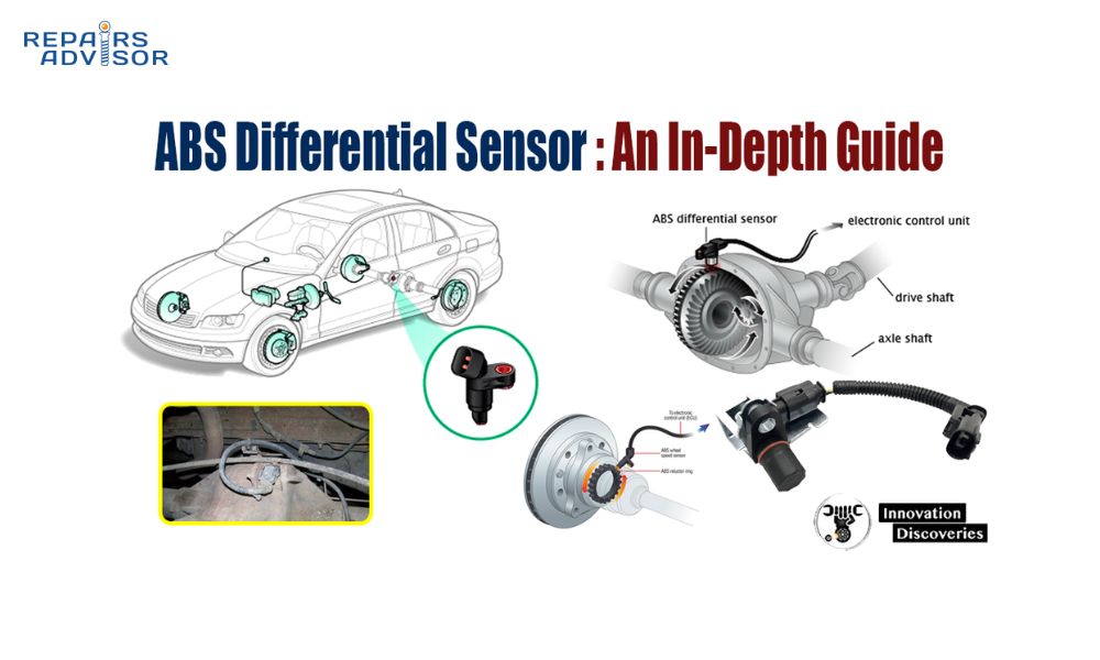
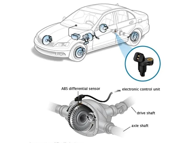
The ABS differential sensor is a specialized electronic component that serves as the eyes and ears of your vehicle’s anti-lock braking system. Unlike the more common wheel-mounted speed sensors found on most passenger vehicles, differential-mounted sensors are typically located on the differential housing of commercial vehicles, trucks, and some rear-wheel-drive applications.
This critical sensor continuously monitors the rotational speed of your vehicle’s differential, which directly correlates to wheel speed and overall vehicle movement. The sensor generates electrical signals based on the rotation of a toothed ring or tone wheel, sending this vital information to the ABS control module dozens of times per second.
Key Distinction from Wheel-Mounted Sensors
While many modern passenger cars use individual wheel speed sensors mounted at each wheel hub, differential-mounted ABS sensors serve a different purpose and are found in specific applications. These sensors are commonly used in:
Commercial and Heavy-Duty Vehicles: Construction and equipment vehicles, delivery trucks, and large commercial vehicles often rely on differential sensors due to their robust design and ability to withstand harsh operating conditions.
Agricultural Equipment: Many agriculture and equipment applications use differential sensors because they provide reliable speed monitoring even in challenging environments with dirt, debris, and moisture.
Truck Applications: Both light and heavy-duty trucks may incorporate differential sensors, particularly in rear-wheel-drive configurations where monitoring the differential provides accurate vehicle speed data.
Integration with Modern Safety Systems
The ABS differential sensor doesn’t work in isolation. Modern vehicles integrate this sensor data with multiple safety systems, including Electronic Stability Control (ESC), Traction Control System (TCS), and hill-start assist functionality. When your differential sensor provides accurate speed information, these systems can make split-second decisions to enhance vehicle stability and control.
The sensor’s data helps determine when wheels are beginning to slip, when the vehicle is losing traction, or when emergency braking intervention is needed. This integration makes the differential sensor a cornerstone component in your vehicle’s overall safety architecture.
How Does an ABS Differential Sensor Work?
The ABS differential sensor operates on the fundamental principles of electromagnetic induction, a reliable technology that has proven effective in automotive applications for decades. Understanding this operation helps you appreciate both the sensor’s capabilities and its potential failure points.
Technical Operation Principles
The sensor consists of a magnetic pickup that detects changes in magnetic field strength as a toothed wheel (tone ring or reluctor ring) rotates past it. As each tooth passes the sensor, it creates a momentary change in the magnetic field, generating a small electrical pulse. The frequency of these pulses directly correlates to the rotational speed of the differential.
Electromagnetic Induction Process: When the differential rotates, the tone ring’s teeth alternately approach and move away from the sensor’s magnetic core. This creates a fluctuating magnetic field that induces voltage changes in the sensor’s coil windings. These voltage changes are converted into digital signals that the ABS control module can interpret as speed data.
Signal Conversion and Transmission: Modern differential sensors typically produce either analog sine wave signals or digital square wave signals. The ABS control module processes these signals to calculate precise rotational speed, acceleration, and deceleration rates.
Component Interaction
The differential sensor system consists of several critical components working in harmony:
Tone Ring/Reluctor Ring Function: This toothed wheel is permanently attached to the differential housing or output shaft. The number of teeth is precisely engineered to provide accurate speed resolution. A typical tone ring might have 60 to 100 teeth, allowing the system to detect very small changes in rotational speed.
Sensor Positioning and Mounting: The sensor must be positioned at a specific distance from the tone ring, typically between 0.5mm to 2.0mm depending on the application. This air gap is critical for proper signal generation. Too large a gap results in weak signals, while too small a gap risks physical contact and damage.
Data Transmission to ABS Control Module: The sensor connects to the vehicle’s main wiring harness through a weatherproof connector. The signal travels to the ABS control module, where sophisticated algorithms process the speed information and determine appropriate system responses.
Types of ABS Differential Sensors
Passive (Inductive) Sensors: These traditional sensors generate their own electrical signal through electromagnetic induction. They’re simple, reliable, and don’t require external power, but they produce relatively weak signals and can’t detect stationary or very slow movement.
Active (Hall Effect) Sensors: These newer sensors require external power but produce stronger, more precise signals. They can detect movement at any speed, including zero speed, making them ideal for advanced stability control systems.
Digital vs. Analog Signal Transmission: While older sensors produced analog sine wave signals, modern sensors increasingly use digital square wave outputs that provide cleaner signals with better noise immunity.
System Integration
Communication with ECM/PCM: The differential sensor data integrates with the vehicle’s main engine control systems, providing speed information for transmission shift control, cruise control, and other functions beyond just ABS operation.
Real-Time Speed Calculation: The ABS control module performs continuous calculations, comparing differential speed with individual wheel speeds (where available) to detect potential lockup conditions.
Brake Pressure Modulation Triggers: When the sensor data indicates impending wheel lockup, the control module signals the ABS pump to modulate brake pressure, preventing lockup while maintaining maximum braking effectiveness.
Common Symptoms of a Failing ABS Differential Sensor
Recognizing the symptoms of a failing ABS differential sensor can help you address problems before they compromise your vehicle’s safety systems. These symptoms range from obvious warning lights to subtle changes in vehicle behavior that might be easy to overlook.
Primary Warning Indicators
ABS Warning Light Activation: The most obvious sign of sensor trouble is the illumination of the ABS warning light on your dashboard. This amber or red light indicates that the ABS system has detected a fault and may have disabled anti-lock braking functionality to prevent unpredictable behavior.
Traction Control Light Illumination: Since traction control systems rely on the same speed data as ABS, a faulty differential sensor often triggers the traction control warning light as well. You may notice this light appearing alongside or shortly after the ABS light.
Electronic Stability Control Warnings: Modern vehicles with ESC systems will typically display stability control warnings when differential sensor data becomes unreliable. The system may disable itself to prevent incorrect interventions that could destabilize the vehicle.
Performance-Related Symptoms
Loss of Anti-Lock Braking Function: With a faulty sensor, your brakes will still function normally under typical conditions, but you’ll lose the anti-lock capability during emergency braking. You may experience wheel lockup and loss of steering control during panic stops.
Increased Stopping Distances: While ABS systems are primarily designed for maintaining control rather than reducing stopping distance, a malfunctioning system can result in longer stopping distances, particularly on slippery surfaces where wheel lockup occurs.
Vehicle Instability During Braking: Without proper speed feedback, the ABS system cannot effectively prevent wheel lockup. This can result in the vehicle pulling to one side during braking or experiencing unpredictable handling characteristics.
Brake Pedal Pulsation Issues: Normally, ABS activation creates a characteristic pedal pulsation during emergency braking. With a faulty sensor, you might experience irregular pulsation patterns or no pulsation when ABS should be active.
Advanced System Malfunctions
Traction Control System Failure: Modern traction control systems depend on accurate wheel speed data to function properly. A faulty differential sensor can cause the traction control system to either fail to activate when needed or activate inappropriately.
Hill-Start Assist Deactivation: Vehicles equipped with hill-start assist rely on speed sensors to detect when the vehicle is on an incline and prevent rollback. Sensor failure can disable this helpful feature.
Electronic Stability Control Loss: ESC systems use differential and wheel speed data to detect vehicle instability. Without reliable sensor input, these systems cannot function properly, potentially leaving you without electronic assistance during emergency maneuvers.
Secondary Symptoms
Check Engine Light Activation: In some vehicles, ABS sensor problems can trigger the check engine light, particularly if the sensor data is used for other engine management functions like transmission control.
Transmission Shifting Issues: Some vehicles use ABS sensor data for transmission shift timing. A faulty sensor might cause irregular shifting patterns or the transmission to remain in a lower gear.
Limp Mode Activation: Severe sensor failures can sometimes trigger limp mode in vehicles where ABS data is integrated with engine management systems, limiting performance until the issue is resolved.
Speedometer Irregularities: If your vehicle uses the differential sensor for speedometer input, you may notice erratic speedometer readings or a non-functional speedometer.
Environmental Condition Impacts
Reduced Performance on Wet Surfaces: Without functioning ABS, your vehicle becomes much more prone to wheel lockup on wet pavement, significantly increasing the risk of losing control during emergency braking situations.
Loss of Control on Icy Conditions: Ice and snow conditions become particularly dangerous without ABS functionality. The system’s ability to prevent wheel lockup while maintaining steering control is crucial for winter driving safety.
Compromised Braking on Gravel/Loose Surfaces: ABS systems are especially beneficial on loose surfaces like gravel where wheel lockup can cause loss of control. Without a functioning sensor, you lose this important safety feature.
Causes of ABS Differential Sensor Failure
Understanding why ABS differential sensors fail helps you prevent problems and make informed decisions about repairs and maintenance. These sensors face challenging operating conditions and can fail for various reasons ranging from environmental factors to normal wear and tear.
Environmental Factors
Dirt and Debris Accumulation: The differential housing area is exposed to road debris, mud, and dirt that can accumulate around the sensor. This buildup can interfere with the sensor’s ability to detect the tone ring’s rotation, causing intermittent or complete signal loss.
Moisture and Corrosion Damage: Water intrusion is one of the most common causes of sensor failure. Moisture can enter through damaged connector seals or housing cracks, causing internal corrosion and short circuits. Road salt accelerates this corrosion process, particularly in winter climates.
Road Salt and Chemical Exposure: De-icing chemicals and road salt create a highly corrosive environment around the differential area. These chemicals can attack sensor housings, wiring, and connectors, leading to premature failure.
Temperature Extremes Impact: Differential sensors must operate in temperature ranges from well below freezing to over 200°F (93°C) from differential heat. Repeated thermal cycling can cause component degradation and eventual failure.
Mechanical Damage
Physical Impact from Road Debris: The differential’s location makes sensors vulnerable to impact damage from rocks, road debris, and objects thrown up by tires. Even minor impacts can damage the sensor housing or misalign the sensor relative to the tone ring.
Tone Ring Damage or Misalignment: The tone ring can become damaged from impact or differential service work. Bent, cracked, or missing teeth create irregular signals that the ABS control module interprets as sensor failure.
Sensor Mounting Bracket Failure: Vibration and thermal expansion can loosen or crack sensor mounting brackets, allowing excessive movement that affects the critical air gap between sensor and tone ring.
Wiring Harness Damage: The wiring harness connecting the sensor to the vehicle’s electrical system is exposed to road hazards, heat, and movement. Chafing, cuts, or crushing can interrupt signal transmission.
Electrical Issues
Short Circuits in Wiring: Water intrusion, chafing, or insulation breakdown can cause short circuits that damage both the sensor and potentially the ABS control module. Short circuits often result in blown fuses and complete system failure.
Open Circuits from Wire Breaks: Flexing, vibration, and corrosion can cause wire breaks that create open circuits. These failures often produce intermittent symptoms that can be difficult to diagnose.
Connector Corrosion and Looseness: Electrical connectors in the differential area face harsh conditions. Corrosion on connector pins creates high resistance connections that can cause signal degradation and eventual failure.
Power Supply Problems: Active sensors require clean, stable power supply voltage. Problems with the vehicle’s charging system or ABS control module power circuits can cause sensor malfunction.
Age and Wear Factors
Normal Sensor Degradation: Like all electronic components, ABS sensors gradually degrade over time. Magnetic strength can weaken, and electronic components can drift out of specification, eventually causing failure.
Magnetic Field Weakening: Passive sensors rely on permanent magnets that can lose strength over time, especially when exposed to heat and vibration. Weak magnetic fields result in poor signal strength and unreliable operation.
Internal Component Failure: Electronic components within the sensor can fail due to age, heat cycling, and vibration. These failures often occur gradually, starting with intermittent symptoms before complete failure.
Wiring Insulation Breakdown: Wire insulation becomes brittle with age and heat exposure, leading to cracks that allow moisture intrusion and short circuits.
Diagnostic Procedures for ABS Differential Sensor Issues
Proper diagnosis of ABS differential sensor problems requires a systematic approach that combines visual inspection, electronic testing, and logical troubleshooting procedures. Accurate diagnosis ensures you replace only the components that have actually failed, saving time and money while ensuring reliable repairs.
Initial Visual Inspection
Locating the Differential Sensor: Begin by identifying the sensor’s location on your specific vehicle. Consult your service manual for exact positioning, as sensor locations vary significantly between manufacturers and vehicle types. Most differential sensors are mounted on the differential housing, transmission case, or transfer case.
Checking for Obvious Damage: Examine the sensor housing for cracks, impact damage, or signs of overheating. Look for oil leaks that might indicate seal failure allowing contaminants to reach the sensor. Check that the sensor is properly seated in its mounting location.
Inspecting Wiring and Connectors: Trace the sensor wiring from the sensor to the main harness connection. Look for chafed, cut, or corroded wires. Pay particular attention to areas where the harness might contact moving parts or sharp edges. Inspect connector housings for cracks, corrosion, or bent pins.
Assessing Tone Ring Condition: Where accessible, inspect the tone ring for damaged, missing, or bent teeth. Look for oil contamination or debris buildup that might interfere with sensor operation. Check for proper alignment and secure mounting.
OBD-II Diagnostic Scanning
Required Diagnostic Tools: Use a quality OBD-II scanner capable of accessing ABS-specific diagnostic trouble codes (DTCs). Professional-grade scanners provide more detailed information than basic code readers and can access manufacturer-specific codes that basic scanners miss.
Reading ABS-Specific Fault Codes: Access the ABS system through your scanner and retrieve all stored and pending fault codes. Document all codes before clearing them, as this information helps identify patterns and related problems. Common codes for differential sensor issues include speed signal missing, implausible signal, or electrical circuit faults.
Live Data Parameter Monitoring: Monitor live ABS sensor data while the vehicle is running. Compare differential sensor readings with wheel speed sensors (if equipped) to identify discrepancies. Look for erratic readings, missing signals, or values that don’t change appropriately with vehicle speed.
Freeze Frame Data Analysis: Examine freeze frame data associated with ABS fault codes. This information shows vehicle operating conditions when the fault occurred, helping identify whether problems occur under specific circumstances like startup, acceleration, or braking.
Advanced Diagnostic Techniques
Multimeter Voltage Testing: Test sensor power supply and signal voltages using a digital multimeter. Active sensors typically require 5V or 12V power supply, while passive sensors generate their own signal voltage. Compare measured values to manufacturer specifications.
Oscilloscope Signal Analysis: For detailed signal analysis, use an oscilloscope to examine sensor output patterns. Proper sensor signals show consistent amplitude and frequency that correlate with rotational speed. Look for signal dropouts, irregular patterns, or amplitude variations that indicate sensor problems.
Resistance Measurements: Test sensor resistance using an ohmmeter with the sensor disconnected. Passive sensors typically show specific resistance values (often 800-1400 ohms), while open or short circuits indicate internal sensor failure.
Signal Pattern Verification: Compare sensor signal patterns between different speeds and operating conditions. Proper sensors produce clean, consistent signals that increase in frequency with increased speed.
Systematic Troubleshooting Approach
Isolating Electrical vs. Mechanical Issues: Begin by determining whether the problem is electrical (wiring, connections, sensor electronics) or mechanical (tone ring, mounting, physical damage). Electrical problems often produce consistent symptoms, while mechanical issues may be intermittent.
Testing Sensor Signal Integrity: Use appropriate test equipment to verify that the sensor produces proper signals under various conditions. Test at idle, during acceleration, and while rotating wheels by hand (with vehicle safely supported).
Verifying Tone Ring Alignment: Ensure the tone ring is properly aligned with the sensor and that the air gap meets manufacturer specifications. Most applications require 0.5-2.0mm gap, but always verify the exact specification for your vehicle.
Checking Air Gap Specifications: Use appropriate gauges to measure the air gap between sensor and tone ring. Excessive gap reduces signal strength, while insufficient gap risks physical contact and damage.
Professional Diagnostic Considerations
When to Use Advanced Scan Tools: Complex intermittent problems may require professional-level diagnostic equipment that can monitor multiple parameters simultaneously and perform actuator tests. These tools often provide guided diagnostic procedures specific to your vehicle.
Manufacturer-Specific Procedures: Different manufacturers use varying diagnostic procedures and specifications. Always consult the appropriate service manual for your specific vehicle rather than relying on generic procedures.
Safety Precautions During Testing: Always follow proper safety procedures when testing ABS components. Ensure the vehicle is properly supported, use appropriate personal protective equipment, and never attempt to test systems while driving.
Documentation Requirements: Document all test results, fault codes, and repair procedures. This documentation helps track recurring problems and provides valuable information for warranty claims or future service.
Step-by-Step Replacement Guide
Replacing an ABS differential sensor requires careful attention to detail and proper procedures to ensure reliable operation and system safety. This comprehensive guide walks you through each step of the replacement process while emphasizing critical safety considerations.
Pre-Replacement Preparation
Required Tools and Equipment: Gather all necessary tools before beginning work. You’ll typically need basic hand tools (wrenches, sockets, screwdrivers), a torque wrench, digital multimeter, and possibly specialized tools for accessing the differential area. Have a quality OBD-II scanner available for post-installation testing.
Safety Equipment and Precautions: Always use appropriate personal protective equipment including safety glasses, work gloves, and steel-toe boots. Ensure you have proper vehicle lifting equipment rated for your vehicle’s weight, including quality jack stands that meet safety standards.
Vehicle Preparation and Positioning: Park the vehicle on level ground and engage the parking brake. If working on a rear differential sensor, you may need to remove the rear wheels and access the differential from underneath the vehicle. Plan your lifting strategy to provide safe, stable access to the work area.
Parts Identification and Procurement: Verify the exact sensor part number for your specific vehicle before ordering replacement parts. ABS sensors are often vehicle-specific, and using the wrong sensor can cause system malfunctions. Consider purchasing a new mounting bolt if the original shows signs of corrosion or damage.
Sensor Location and Access
Lifting and Supporting the Vehicle: Follow proper lifting procedures for your vehicle type. Use designated jack points and never rely solely on a hydraulic jack for support. Position jack stands securely and test stability before working under the vehicle. For some applications, you may need to remove wheels to access the differential area.
Identifying Differential Sensor Location: Locate the sensor on the differential housing, transmission case, or transfer case according to your service manual. The sensor typically mounts with a single bolt and connects via a waterproof electrical connector. Take photos of the sensor position and wiring routing for reference during installation.
Removing Protective Covers or Shields: Some vehicles have protective covers or splash shields that must be removed to access the sensor. Remove these carefully and keep track of all fasteners. Clean the area around the sensor to prevent dirt contamination during the replacement process.
Accessing Electrical Connections: The sensor electrical connector may be located near the sensor or routed to a junction point elsewhere on the vehicle. Trace the wiring carefully and identify the connector location before attempting removal.
Removal Procedure
Disconnecting Electrical Connector: Carefully disconnect the sensor electrical connector by releasing any locking tabs or clips. Avoid pulling on the wires themselves, as this can damage the connector or wiring. If the connector is corroded or difficult to remove, use appropriate electrical contact cleaner and gentle pressure.
Removing Sensor Mounting Bolt: Remove the sensor mounting bolt using the appropriate socket or wrench. These bolts are often exposed to harsh conditions and may be corroded or seized. If the bolt is difficult to remove, use penetrating oil and allow time for it to work. Avoid using excessive force that might damage the differential housing threads.
Extracting Old Sensor Carefully: Remove the old sensor from its mounting hole, being careful not to drop it or allow debris to fall into the differential. Some sensors may be held firmly by magnetic attraction to the tone ring, requiring steady pulling force to remove.
Cleaning Sensor Mounting Area: Thoroughly clean the sensor mounting hole and surrounding area using appropriate cleaning solvents. Remove all old sealant, dirt, and corrosion. Inspect the mounting hole for damage and ensure the tone ring is clean and undamaged.
Installation of New Sensor
Applying Thread Locker if Specified: Some applications require thread locker on the sensor mounting bolt to prevent loosening from vibration. Use only the type and amount specified in your service manual, as excessive thread locker can make future removal difficult.
Proper Sensor Positioning and Alignment: Install the new sensor carefully, ensuring it’s properly seated in the mounting hole. The sensor should slide in easily without forcing. If resistance is encountered, verify that no debris is blocking the hole and that the sensor is correctly oriented.
Torque Specifications for Mounting Bolt: Tighten the sensor mounting bolt to the manufacturer’s specified torque value. This specification is critical because insufficient torque can allow sensor movement, while excessive torque can damage the sensor housing or differential threads.
Reconnecting Electrical Connector: Connect the electrical connector firmly, ensuring all locking tabs or clips are properly engaged. The connection should be secure and weatherproof. Apply dielectric grease to connector pins if specified by the manufacturer.
Post-Installation Procedures
Clearing Diagnostic Trouble Codes: Use your OBD-II scanner to clear all ABS-related fault codes from the vehicle’s memory. This ensures that old codes don’t interfere with testing the new sensor’s operation.
Test Driving and System Verification: Perform a careful test drive in a safe area to verify proper system operation. The ABS warning light should turn off after a few minutes of driving if the repair was successful. Test ABS operation carefully in a safe environment if possible.
Final Functionality Testing: Use your scanner to monitor live sensor data and verify that the new sensor is producing appropriate signals. Compare readings with other sensors and ensure values change appropriately with vehicle speed.
Documentation of Repair: Record all repair information including part numbers, torque specifications, and test results. This documentation is valuable for warranty purposes and future service needs.
For complex diagnostic procedures or if you encounter difficulties during replacement, consult detailed repair manuals specific to your vehicle. Consider seeking professional assistance if you’re unsure about any aspect of the procedure, as brake system components are critical for vehicle safety.
Prevention and Maintenance Tips
Proactive maintenance and prevention strategies can significantly extend the life of your ABS differential sensor while ensuring consistent performance of your vehicle’s safety systems. Regular attention to these components is far more cost-effective than dealing with unexpected failures.
Regular Inspection Schedule
Visual Checks During Routine Maintenance: Incorporate ABS sensor inspection into your regular maintenance routine. During oil changes or other under-vehicle service, take time to visually inspect the sensor, wiring, and mounting area. Look for signs of damage, corrosion, or contamination that could lead to future problems.
Cleaning Sensor and Surrounding Area: Keep the differential area clean and free from excessive buildup of dirt, mud, and road debris. While some contamination is inevitable, excessive buildup can interfere with sensor operation and trap moisture that accelerates corrosion.
Monitoring Warning Light Status: Pay attention to your dashboard warning lights and address ABS lights promptly. Ignoring warning lights can lead to more extensive damage and costly repairs. Even intermittent warning lights should be investigated, as they often indicate developing problems.
Professional Brake System Inspections: Have your brake system, including ABS components, inspected by qualified technicians during major service intervals. Professional inspections can identify potential problems before they cause system failures.
Environmental Protection Measures
Keeping Differential Area Clean: Regular washing of the undercarriage helps remove road salt, chemicals, and debris that can damage sensors and wiring. Pay particular attention to the differential area during winter months when road salt use is heavy.
Protecting From Road Salt Exposure: Consider applying undercarriage protection treatments that help repel moisture and reduce corrosion from road salt. These treatments are particularly beneficial in climates with harsh winters.
Addressing Leaks Promptly: Repair differential, transmission, or transfer case leaks promptly. Oil leaks can attract dirt and debris while providing pathways for moisture intrusion that can damage sensors and wiring.
Parking Considerations: When possible, avoid parking in areas where the vehicle’s undercarriage is exposed to standing water, excessive moisture, or corrosive chemicals. Covered parking helps protect all undercarriage components from environmental damage.
Driving Habits for Sensor Longevity
Avoiding Deep Water/Puddles: While modern vehicles can handle normal water crossing, avoiding unnecessarily deep water helps protect electrical components. If you must drive through water, do so slowly to minimize splash and water intrusion.
Gentle Braking Practices: Smooth, progressive braking reduces stress on all brake system components, including ABS sensors. Avoid unnecessary hard braking that forces the ABS system to activate frequently.
Regular ABS System Testing: Periodically test your ABS system in safe conditions to ensure it’s functioning properly. Find a safe, empty parking lot and practice emergency braking techniques to verify system operation.
Prompt Attention to Warning Signs: Address any unusual brake behavior, warning lights, or other symptoms immediately. Early intervention often prevents minor problems from becoming major repairs.
Cost Considerations and Professional vs. DIY
Understanding the costs associated with ABS differential sensor replacement helps you make informed decisions about repair approaches and budget planning. Consider both immediate costs and long-term value when choosing between professional service and DIY repair.
Replacement Cost Breakdown
OEM vs. Aftermarket Sensor Pricing: Original Equipment Manufacturer (OEM) sensors typically cost $75-150 for most applications, while quality aftermarket sensors range from $45-100. Premium aftermarket brands often provide OEM-equivalent performance at lower cost, while economy sensors may have shorter service life.
Labor Cost Estimates: Professional installation typically requires 1-2 hours of labor, with shop rates varying from $100-150 per hour depending on location and shop type. Dealership service departments often charge higher rates but provide manufacturer-specific expertise and warranty coverage.
Additional Parts That May Be Needed: Budget for potential additional parts including mounting bolts ($5-15), wiring harness repairs ($25-75), or tone ring replacement if damaged ($50-150). These costs can add significantly to the total repair bill if problems are discovered during service.
Geographic Cost Variations: Labor rates and parts availability vary significantly by location. Urban areas typically have higher labor costs but better parts availability, while rural areas may have lower labor rates but longer parts delivery times.
DIY Feasibility Assessment
Required Skill Level Evaluation: ABS sensor replacement requires intermediate mechanical skills including ability to safely lift and support vehicles, use basic tools effectively, and follow technical procedures. The job is within reach of most DIY enthusiasts with proper preparation and tools.
Tool Requirements and Costs: Basic tool requirements include standard hand tools, torque wrench, and OBD-II scanner. If you don’t own these tools, purchase or rental costs should be factored into your decision. Quality tools are a good investment for multiple future repairs.
Time Investment Considerations: Plan for 2-4 hours for DIY replacement, including preparation, actual repair work, and testing. Factor in additional time for parts procurement and potential complications that may arise during the repair process.
Potential Complications: DIY repairs can encounter complications including seized bolts, damaged wiring, or access difficulties. Consider your comfort level with problem-solving and ability to complete the repair if unexpected issues arise.
When to Seek Professional Help
Complex Diagnostic Requirements: If multiple fault codes are present or symptoms suggest system-wide problems, professional diagnosis may be more cost-effective than trial-and-error parts replacement.
Specialized Tool Needs: Some vehicles require special tools for sensor access or calibration procedures that aren’t cost-effective for single-use DIY repairs.
Safety Considerations: Brake system work directly affects vehicle safety. If you’re unsure about any aspect of the repair or lack proper equipment, professional service ensures the job is done correctly.
Warranty Implications: Professional repairs often include parts and labor warranties that provide protection against defective components or installation errors. Consider the value of warranty coverage in your decision.
Related ABS System Components
Understanding how ABS differential sensors interact with other system components helps you recognize potential problems and make informed repair decisions. The ABS system functions as an integrated unit where component failures can affect multiple system functions.
ABS Control Module Function
The ABS control module serves as the brain of the entire system, processing sensor data and controlling brake pressure modulation. This sophisticated computer monitors all sensor inputs continuously, comparing actual wheel speeds with calculated expected speeds to detect potential lockup conditions.
When your differential sensor provides data to the control module, complex algorithms process this information alongside other inputs to determine appropriate system responses. The control module can detect sensor failures by comparing differential sensor data with individual wheel sensors and identifying inconsistencies that indicate problems.
Hydraulic Control Unit Operation
The hydraulic control unit, often integrated with the ABS pump, receives commands from the control module to modulate brake pressure. When differential sensor data indicates potential wheel lockup, the hydraulic unit rapidly cycles brake pressure to individual wheels or wheel groups.
This system relies on accurate sensor data to function properly. Faulty differential sensor information can cause inappropriate pressure modulation, reducing braking effectiveness or causing unwanted system activation.
Individual Wheel Speed Sensors
Many vehicles combine differential sensors with individual wheel speed sensors to provide comprehensive speed monitoring. The ABS control module compares data from all sensors to verify accuracy and detect failures. When differential and wheel sensor data don’t correlate properly, the system can often identify which sensor has failed.
Understanding this relationship helps explain why differential sensor failure often triggers multiple warning lights and system shutdowns. The control module prioritizes safety by disabling systems rather than operating with unreliable data.
System Interconnections and Dependencies
Modern ABS systems integrate with numerous other vehicle systems including traction control, stability control, transmission control, and cruise control. Your differential sensor data feeds into many of these systems, making sensor reliability crucial for overall vehicle performance.
When planning repairs, consider that differential sensor problems can affect multiple systems simultaneously. Proper repair and testing ensures all interconnected systems return to normal operation.
Essential Resources for ABS System Maintenance
Manual and Documentation Resources
For comprehensive repair procedures specific to your vehicle, consult manufacturer service manuals available through Repairs Advisor. Our extensive collection includes detailed ABS system documentation for:
- Ford Manuals – Complete ABS diagnostic and repair procedures for Ford vehicles
- Chevrolet Manuals – GM ABS system service information and technical bulletins
- Toyota Manuals – Toyota/Lexus ABS sensor specifications and replacement procedures
- Mercedes Manuals – European vehicle ABS system complexity and diagnostic procedures
Specialized Equipment Applications
Different vehicle categories require specific approaches to ABS sensor service:
- Construction and Equipment – Heavy-duty differential sensor applications and harsh environment considerations
- Agriculture and Equipment – Farm equipment ABS systems and contamination prevention
- Material Handling – Forklift and industrial vehicle ABS sensor maintenance
Additional Technical Resources
Expand your understanding of related brake system components:
- How to Bleed Your Brakes: A Professional Step-by-Step Guide – Essential brake maintenance procedures
- Signs Your ABS Valve Assembly Is Failing – Related ABS component diagnostics
- Vehicle Systems & Parts Explained – Comprehensive automotive system education
Conclusion
Your ABS differential sensor plays a crucial role in maintaining vehicle safety by providing the precise speed data that enables anti-lock braking, traction control, and stability systems to function properly. Understanding how this component works, recognizing failure symptoms, and knowing when to seek professional help can help you maintain these critical safety systems effectively.
Regular maintenance, prompt attention to warning signs, and proper diagnostic procedures ensure your ABS system continues protecting you and your passengers. Whether you choose to perform repairs yourself or seek professional service, the key is addressing problems promptly before they compromise your vehicle’s safety systems.
Remember that brake system components directly affect your safety and the safety of others on the road. When in doubt, consult with qualified professionals who have the expertise and equipment to diagnose and repair ABS system problems correctly.
Disclaimer: This information is provided for reference only and should be implemented at your own risk and responsibility. Always consult your vehicle’s service manual for specific procedures and specifications. Professional consultation is recommended for complex diagnostic procedures, and proper safety equipment is mandatory when performing any brake system work. Vehicle-specific procedures may vary significantly from the general information provided in this guide.